
Electrosurgical ablation apparatus

a technology of electrosurgical ablation and ablation chamber, which is applied in the field of electrosurgical ablation chamber, can solve the problems of affecting the uniform heating of a targeted volume, and reducing the efficiency of the ablation process

Active Publication Date: 2014-12-25
KONINKLJIJKE PHILIPS NV
View PDF2 Cites 36 Cited by
  • Summary
  • Abstract
  • Description
  • Claims
  • Application Information

AI Technical Summary

Benefits of technology

The invention is about improving the efficiency of ablation, which involves heating and destroying tissue, by controlling the frequency of microwave radiation delivered into the tissue. This is particularly important when there is a difference in blood flow or when the targeted volume is not perfectly spherical. By using different frequencies at the same time or one after the other, the ablation process can be more effectively controlled, resulting in better outcomes and minimizing damage to surrounding tissues.

Problems solved by technology

Further, even in case of a substantially uniform dissipation of heat in or from the surroundings of a desired targeted volume, a uniform heating of a targeted volume can be impaired or restricted and the efficiency of the ablation process is accordingly decreased when this volume is not at least substantially spherical, but has for example non symmetrical or arbitrary or irregular extensions.

Method used


Image

  • Electrosurgical ablation apparatus
  • Electrosurgical ablation apparatus
  • Electrosurgical ablation apparatus

Examples


first embodiment

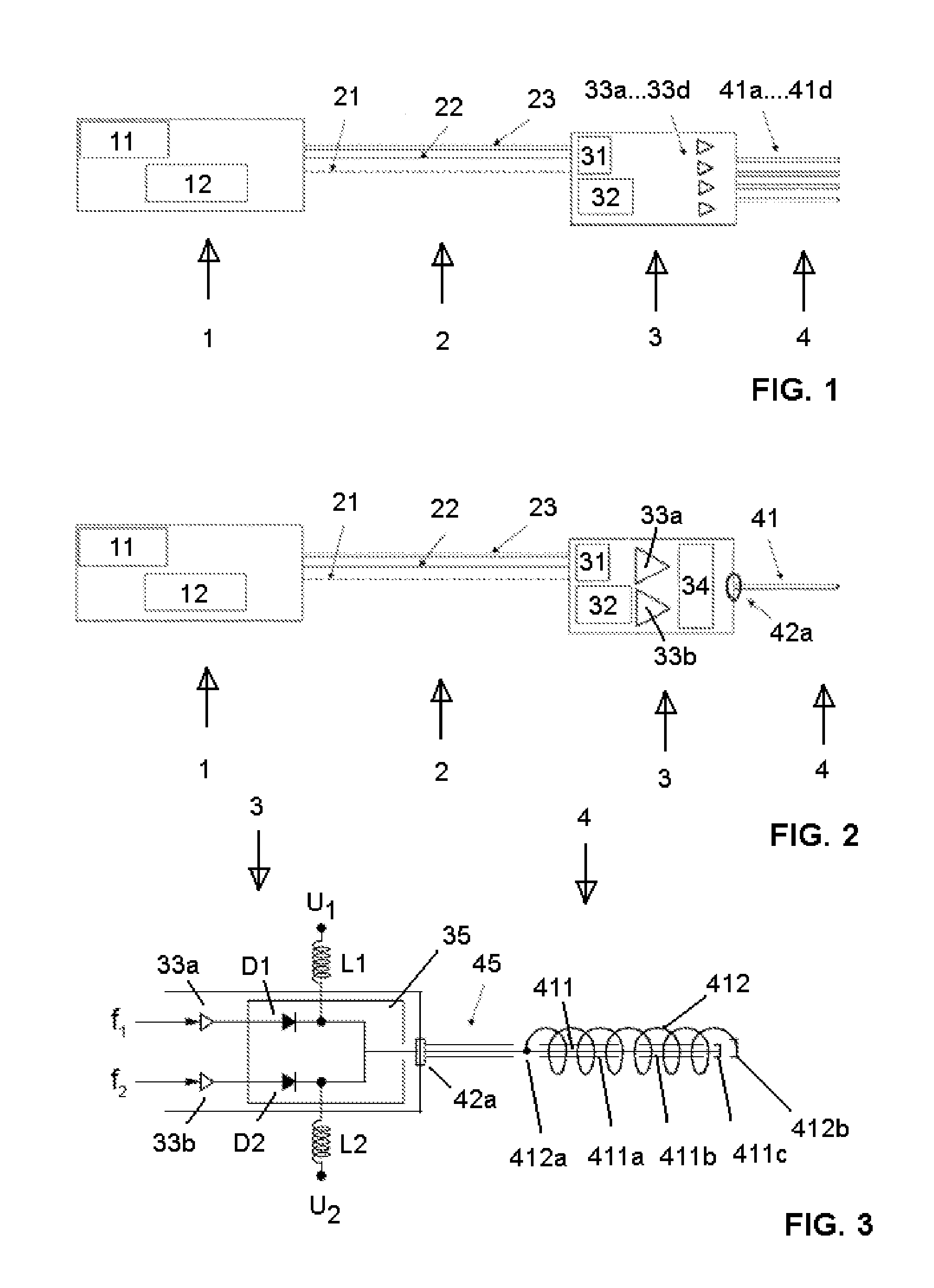
[0044]The same or corresponding units and components as in FIG. 1 are denoted in FIG. 2 with the same or corresponding reference signs. Accordingly, only the differences to the first embodiment shall be explained in the following.

[0045]In contrast to the first set-up, the applicator antenna 4 comprises only one antenna needle 41, which, however, is dimensioned to be dual- or multi-resonant, i.e. it can be excited to resonate (preferably at λ / 4 wavelength) at two (or more) different microwave frequencies as explained below. Accordingly, two (or more) microwave generators and RF power amplifiers 33a, 33b are provided for feeding the antenna needle 41 with RF ablation signals having two (or more) different microwave frequencies (and possible different RF power levels), which can be selected by a user and can be transmitted simultaneously or sequentially. Alternatively, one microwave generator or RF power amplifier can be provided which can be switched between the related two (or more) ...

second embodiment

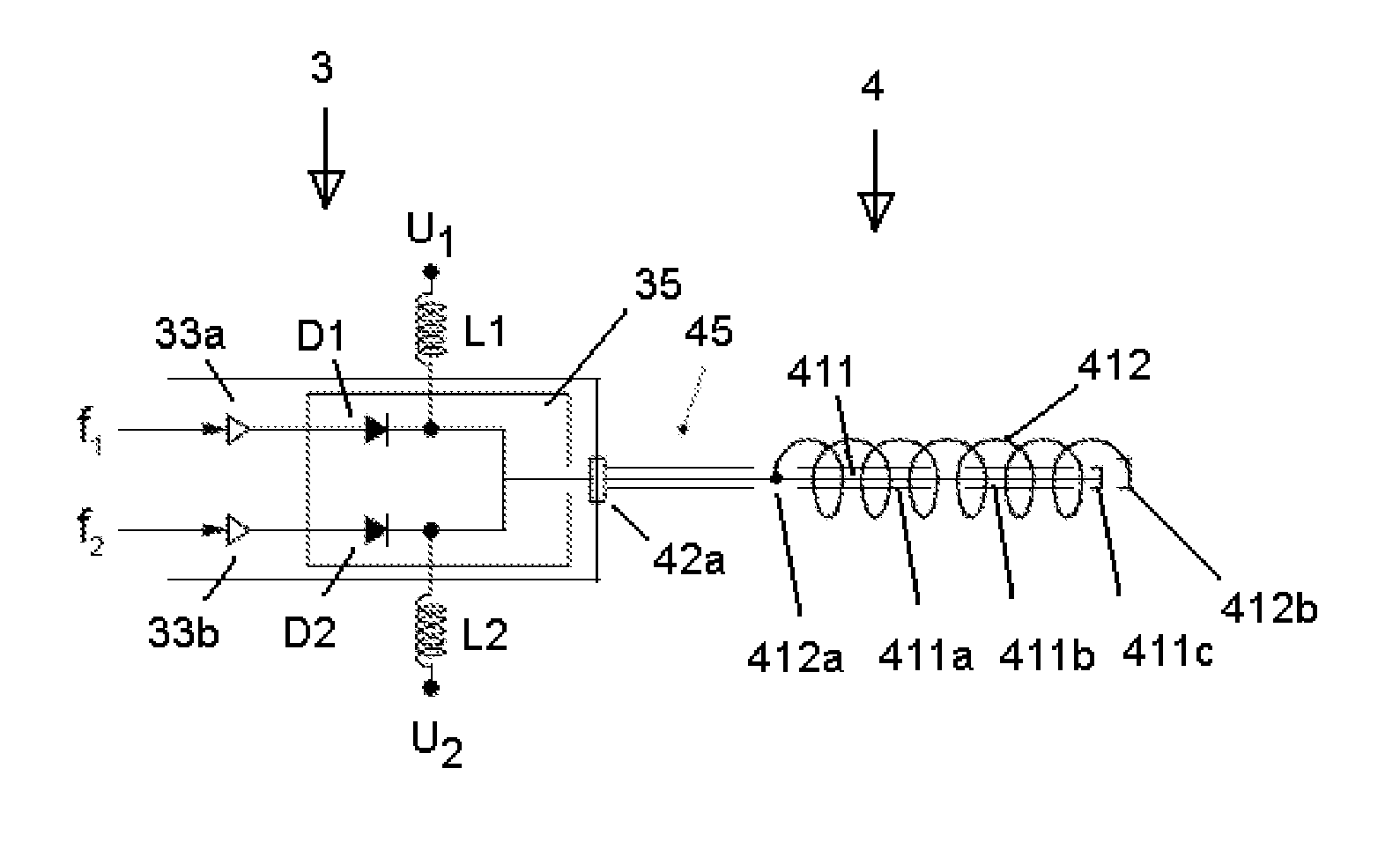
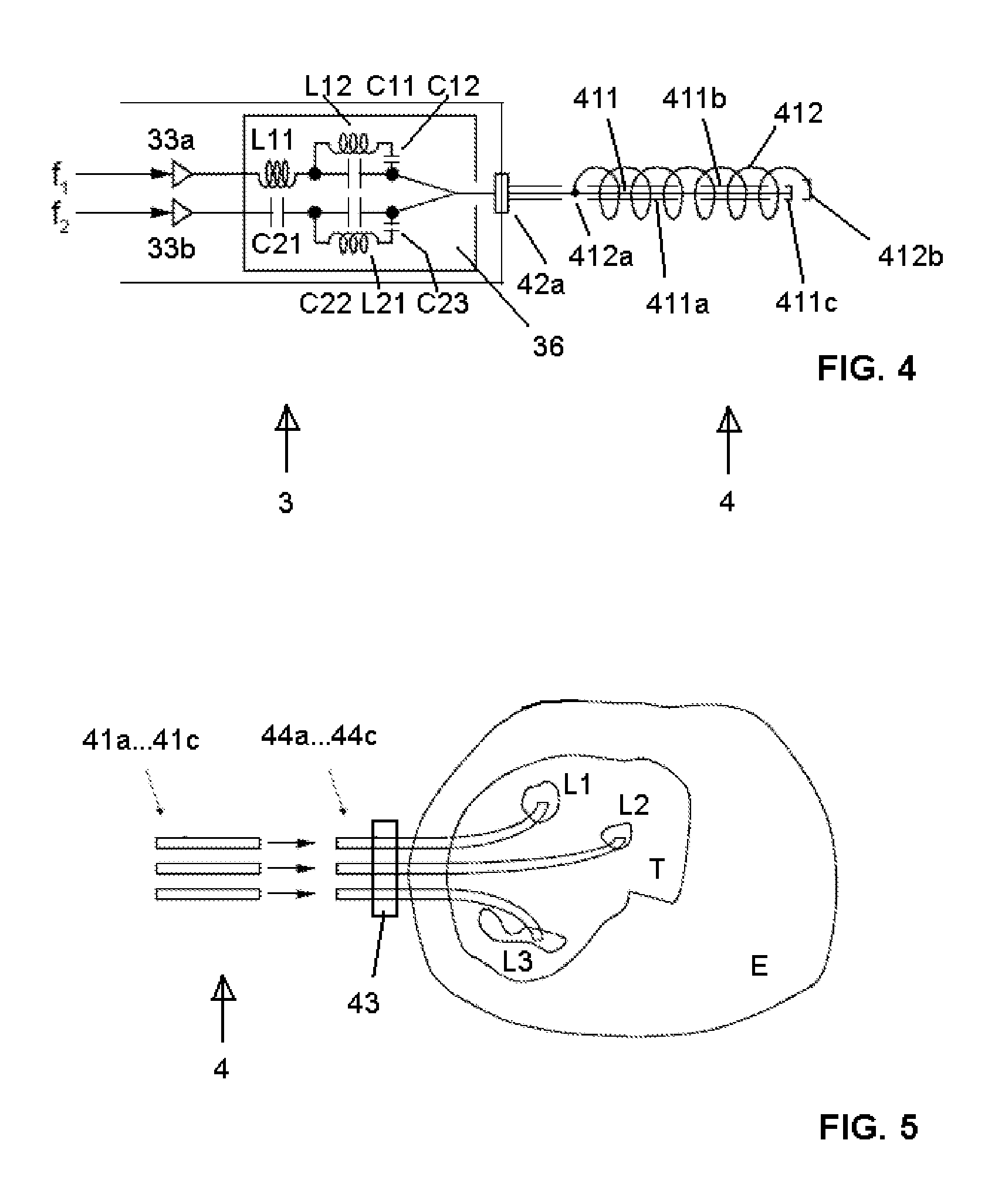
[0057]FIG. 4 schematically shows substantial components of an applicator unit 3 and a dual resonant applicator antenna 4 according to a

[0058]The same or corresponding parts and components as in the first embodiment according to FIG. 3 are denoted with the same or corresponding reference signs. In the following, substantially only the differences to the third embodiment shall be explained.

[0059]Instead of the PIN switch 35, the applicator unit 3 comprises a diplexer 36 in the form of a conventional diversity circuit. Such a circuit 36 has especially three functions, namely combining the first and the second RF ablation signal and decoupling the outputs of the first and the second amplifier 33a, 33b from one another, and matching the impedances at the outputs of the amplifiers to the impedance at the input of the RF ablation antenna. Consequently, this embodiment is especially suitable for simultaneously transmitting the first and the second RF ablation signal.

[0060]Again, the diplexe...


PUM


Abstract

An electrosurgical ablation apparatus for generating and emitting electromagnetic radiation energy for ablating biological tissue is disclosed. The apparatus comprises an operating unit (1), a handheld applicator unit (3) with an applicator antenna (4) and a cable connection (2) between both. The applicator antenna (4) is a dual or multi-resonant ablation antenna (41a, . . . 41d) for transmitting microwave ablation energy at at least two different frequencies which are selected especially according to the electrical properties and dimensions of the tissue to be ablated.

Description

FIELD OF THE INVENTION[0001]The invention relates to an electrosurgical ablation apparatus for generating and emitting electromagnetic radiation energy for ablating biological tissue. Further, the invention relates to a method for electrosurgical ablation under MR imaging control.BACKGROUND OF THE INVENTION[0002]Electromagnetic radiation, especially in the frequency range of microwaves, is frequently used for electrosurgical or hyperthermia therapy in order to ablate or coagulate distinct targeted areas or volumes (especially lesions) of a biological tissue in order to treat various diseases.[0003]In this respect, electromagnetic radiation can effectively heat a tissue especially in at least one of two ways, namely by inducing an electric current in the tissue (if it is electrically conductive), or by inducing a rotation of the dipoles present in water molecules in the tissue (dielectric heating), wherein the rotation of the dipoles changes with changes in the electromagnetic radiat...

Claims


Application Information

Patent Timeline
IPC IPC(8): A61B18/18
CPCA61B18/18A61B2018/00577A61B2018/00005A61B18/1815A61B2018/1846A61B2018/1869A61B2018/1876
Inventor LEUSSLER, CHRISTOPH
Owner KONINKLJIJKE PHILIPS NV
Learn More