Apparatus and method for geothermally cooling electronic devices installed in a subsurface environment

Active Publication Date: 2015-01-01
SMITH DAVID
View PDF4 Cites 11 Cited by
  • Summary
  • Abstract
  • Description
  • Claims
  • Application Information

AI Technical Summary

Problems solved by technology

The increased cooling capability of the subsurface environment is likely to lead to a lower average operating

Method used


Image

  • Apparatus and method for geothermally cooling electronic devices installed in a subsurface environment
  • Apparatus and method for geothermally cooling electronic devices installed in a subsurface environment
  • Apparatus and method for geothermally cooling electronic devices installed in a subsurface environment

Examples


Embodiment Construction

[0024]Although described with reference to certain embodiments, those with skill in the art will recognize that the disclosed embodiments have relevance to a wide variety of areas in addition to the specific examples described below. Further, elements from one or more embodiments may be used in other embodiments and elements may be removed from an embodiment and remain within the scope of this disclosure.

[0025]All references, including publications, patent applications, and patents, cited herein are hereby incorporated by reference to the same extent as if each reference were individually and specifically indicated to be incorporated by reference and were set forth in its entirety herein; provided, however, to the extent there exists a conflict between this disclosure and a document incorporated by reference, this disclosure shall control.

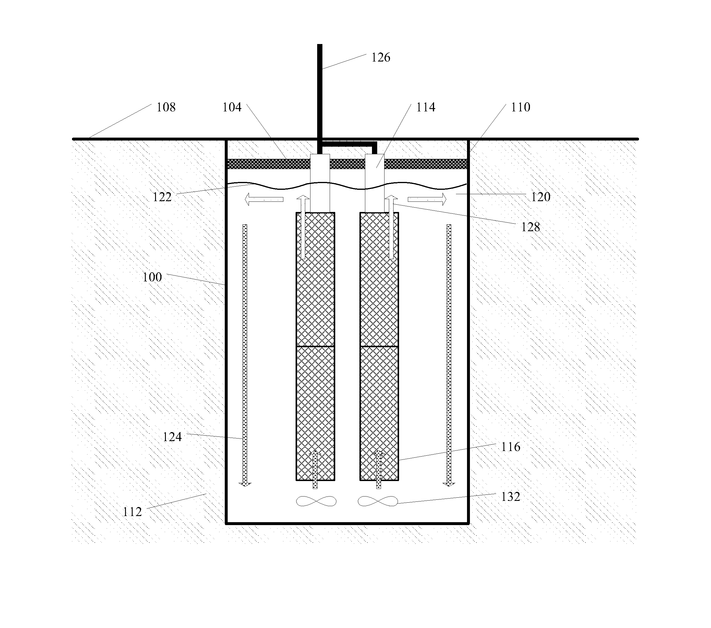
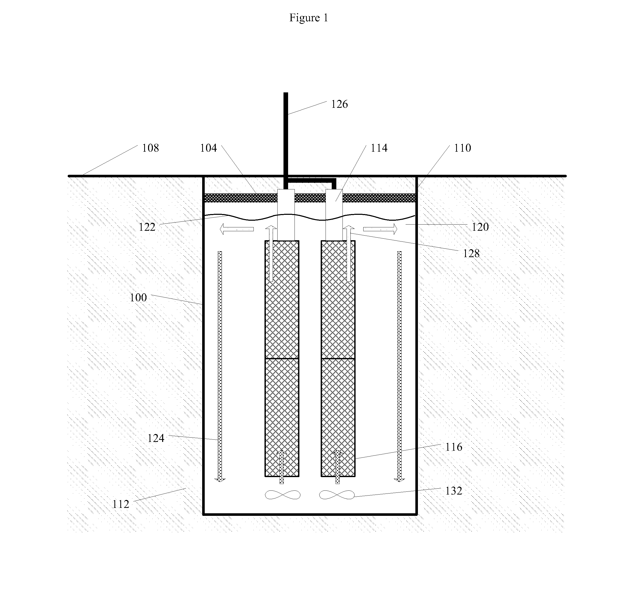
[0026]In its most basic embodiment, the design consists of a computer hardware system, either as an individual unit or as a cluster of units, inst...


PUM


Abstract

An apparatus and method for cooling of electronic equipment, for example a computer system, in a subsurface environment including a containment vessel in at least partial contact with subsurface liquid or solid material. The containment vessel may be disposed in a variety of subsurface environments, including boreholes, man-made excavations, subterranean caves, as well as ponds, lakes, reservoirs, oceans, or other bodies of water. The containment vessel may be installed with a subsurface configuration allowing for human access for maintenance and modification. Geothermal cooling is achieved by one or more fluids circulating inside and/or outside the containment vessel, with a variety of configurations of electronic devices disposed within the containment vessel. The circulating fluid(s) may be cooled in place by thermal conduction or by active transfer of the fluid(s) out of the containment vessel to an external, possibly geothermal, heat exchange mechanism, then back into the containment vessel.

Description

RELATED APPLICATION[0001]This application claims the priority of U.S. Provisional 61 / 698,365, filed on Sep. 7, 2012 and entitled “GEOTHERMALLY COOLED COMPUTER HARDWARE SYSTEM DESIGNED FOR SUBSURFACE INSTALLATION”.TECHNICAL FIELD[0002]This disclosure relates to a system and method for geothermally cooling electronic devices, including but not limited to computer systems, by installing the electronic devices in subsurface environments such as boreholes, excavations, or bodies of water.BACKGROUND[0003]Large-scale data centers typically house hundreds or thousands of computer systems in high-density configurations (side-by-side racks, with multiple computing nodes per rack) in an above-ground building. Some sources estimate that up to 50% of the electrical power consumption for data centers is dedicated to cooling the environment in which the computer systems operate.[0004]The heat generated by the internal electronic components of computing devices has long been a significant factor de...

Claims


Application Information

Patent Timeline
IPC IPC(8): F25D1/00F25B30/06F25D3/00H05K7/20
CPCF25D3/00F25D1/00F25D2331/00H05K7/20218F25B30/06Y02E60/142F28D20/0052H05K7/2079Y02E70/30H05K7/20236Y02E60/14
Inventor SMITH, DAVID
Owner SMITH DAVID
Why Eureka
Try Eureka