Exhaust gas abatement system
a technology of exhaust gas and abatement system, which is applied in the direction of combustion types, lighting and heating apparatus, separation processes, etc., can solve the problems of increasing the running cost of cooling and cleaning water supply, increasing the cost of waste water treatment,
- Summary
- Abstract
- Description
- Claims
- Application Information
AI Technical Summary
Benefits of technology
Problems solved by technology
Method used
Image


Examples
first embodiment
A. First Embodiment
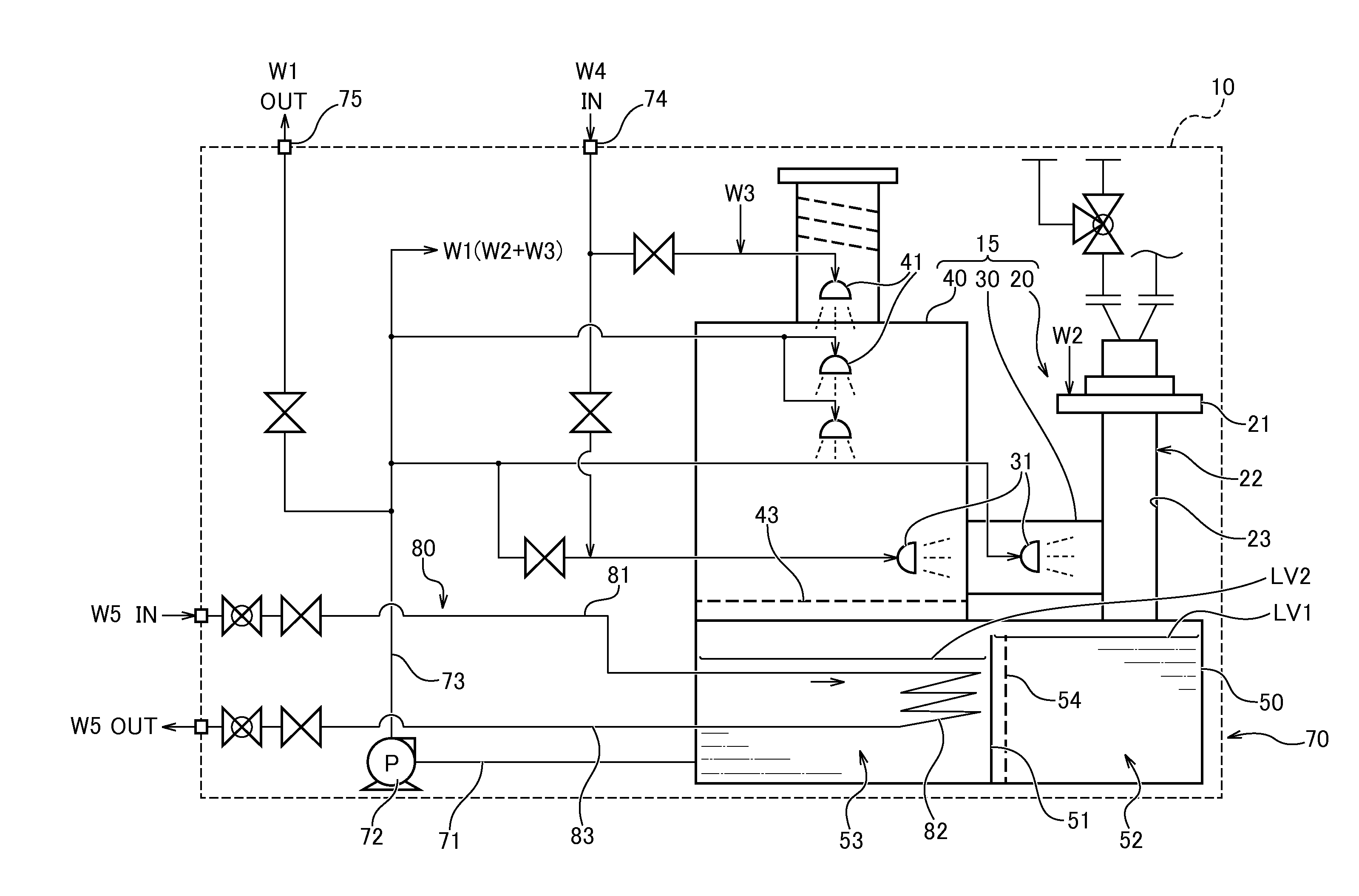
[0025]FIG. 1 shows a schematic configuration of an exhaust gas abatement system 10 as a first embodiment. In this embodiment, the exhaust gas abatement system 10 is an abatement system which abates exhaust gases exhausted in a semiconductor fabrication process before they are discharged to the atmosphere. The exhaust gas abatement system 10 includes an exhaust gas abatement section 15, a water circulating section 70, and a heat exchanger section 80. The exhaust gas abatement section 15 includes an incinerating portion 20, a cooling portion 30, and a cleaning portion 40 and abates exhaust gases by using a circulating water W1. The circulating water W1 may simply be water or a solution to which a predetermined additive (for example, an alkaline agent to neutralize an acidic gas) is added. The water circulating section 70 includes a circulating water storage portion 50, water circulating pipes 71, 73, and a water circulating pump 72, whereby the circulating water W1 ...
second embodiment
B. Second Embodiment
[0048]FIG. 5 shows part of the configuration of an exhaust gas abatement system of a second embodiment. In FIG. 5, like reference numerals are given to like constituent elements to those of the first embodiment (FIG. 1). The exhaust gas abatement system of the second embodiment differs from that of the first embodiment in that a heat exchanger 282 is provided in place of the heat exchange tube 82 in the first embodiment but is similar in the other features to the first embodiment. Hereinafter, the feature different from the first embodiment will be described. The heat exchanger 282 includes a heat exchange tube 82 and a water circulation pipe 288. The heat exchange tube 82 is housed in an interior of the water circulation pipe 288. The water circulation pipe 288 has a horizontally curved shape so as to form a serpentine channel, and the heat exchange tube 82 also has a shape which follows the shape of the water circulation pipe 288. The water circulation pipe 288...
third embodiment
C. Third Embodiment
[0050]FIG. 6 shows part of the configuration of an exhaust gas abatement system of a third embodiment. The third embodiment differs from the first embodiment in that the exhaust gas abatement system includes a first tube group 384a, a second tube group 384b, and header pipes 381a, 382a, 381b, 382b in place of the heat exchange tube 82 of the first embodiment but is similar in the other features to the first embodiment. Hereinafter, the feature of the third embodiment which differs from the first embodiment will be described. The header pipes 381a, 382a are connected to end portions of the first tube group 384a. Similarly, the header pipes 381b, 382b are connected to end portions of the second tube group 384b.
[0051]A cooling water W5 introduced into the header pipe 381b flows through an interior of the second tube group 384b and then flows into the header pipe 382b. The cooling water W5 that has flowed into the header pipe 382b flows into the header pipe 382a and ...
PUM
| Property | Measurement | Unit |
|---|---|---|
| temperatures | aaaaa | aaaaa |
| temperature | aaaaa | aaaaa |
| thermal energy | aaaaa | aaaaa |
Abstract
Description
Claims
Application Information
 - R&D
- Intellectual Property
- Life Sciences
- Materials
- Tech Scout
- Unparalleled Data Quality
- Higher Quality Content
- 60% Fewer Hallucinations
Browse by: Latest US Patents, China's latest patents, Technical Efficacy Thesaurus, Application Domain, Technology Topic, Popular Technical Reports.
© 2025 PatSnap. All rights reserved.Legal|Privacy policy|Modern Slavery Act Transparency Statement|Sitemap|About US| Contact US: help@patsnap.com