Storage battery control device, storage battery control method, program, electricity storage system, and power supply system

a storage battery and control device technology, applied in the direction of storage battery control devices, storage battery control methods, electricity storage systems, etc., can solve the problem of inefficient power output, and achieve the effect of improving performan

Active Publication Date: 2015-01-01
ORMON CORP
View PDF2 Cites 28 Cited by
  • Summary
  • Abstract
  • Description
  • Claims
  • Application Information

AI Technical Summary

Benefits of technology

[0014]According to one aspect of the disclosure, the better performance can

Problems solved by technology

However, although the power supply system disclosed in Patent Document 1 can perform the operation without depending on a specific

Method used


Image

  • Storage battery control device, storage battery control method, program, electricity storage system, and power supply system
  • Storage battery control device, storage battery control method, program, electricity storage system, and power supply system
  • Storage battery control device, storage battery control method, program, electricity storage system, and power supply system

Examples


first embodiment

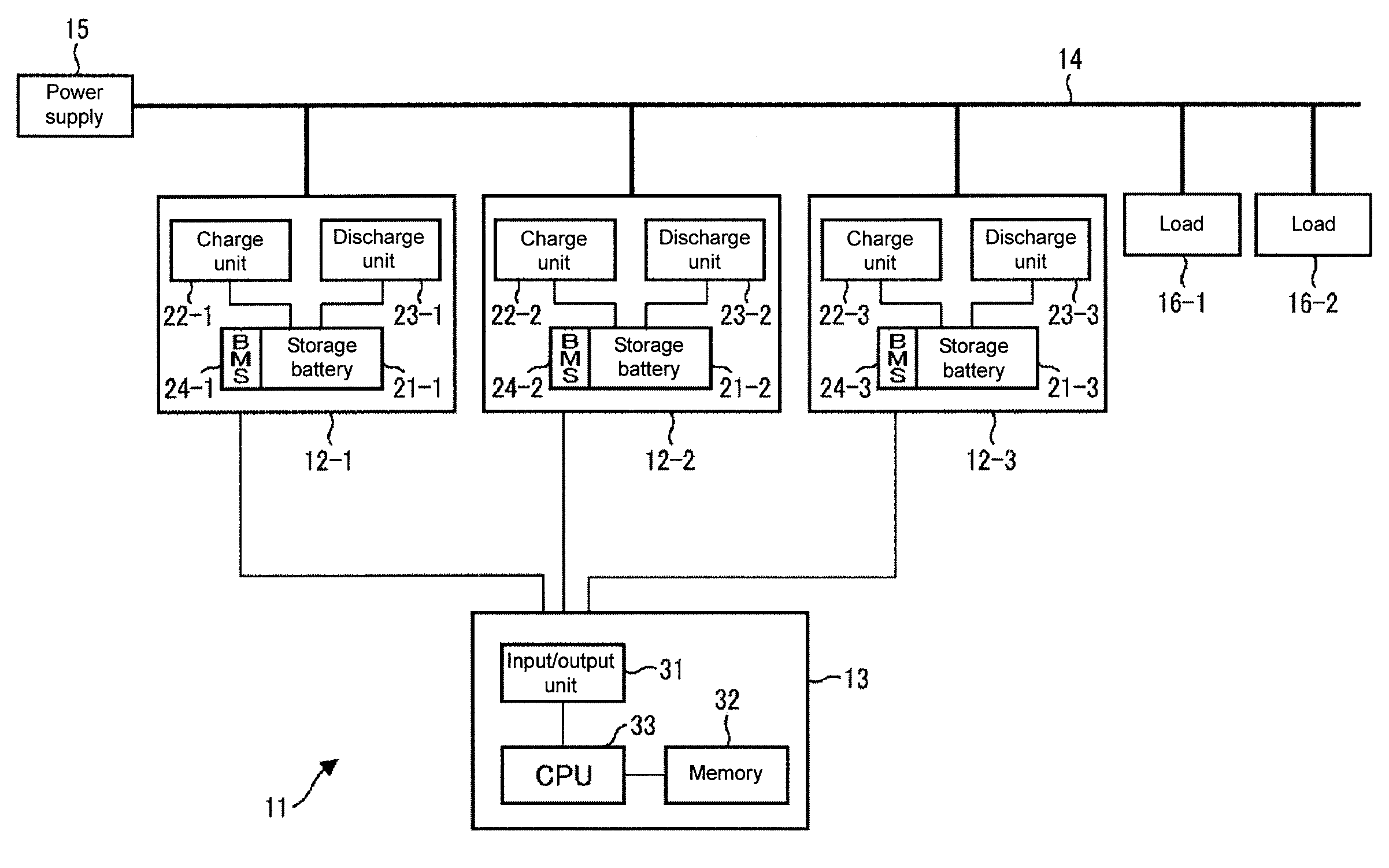
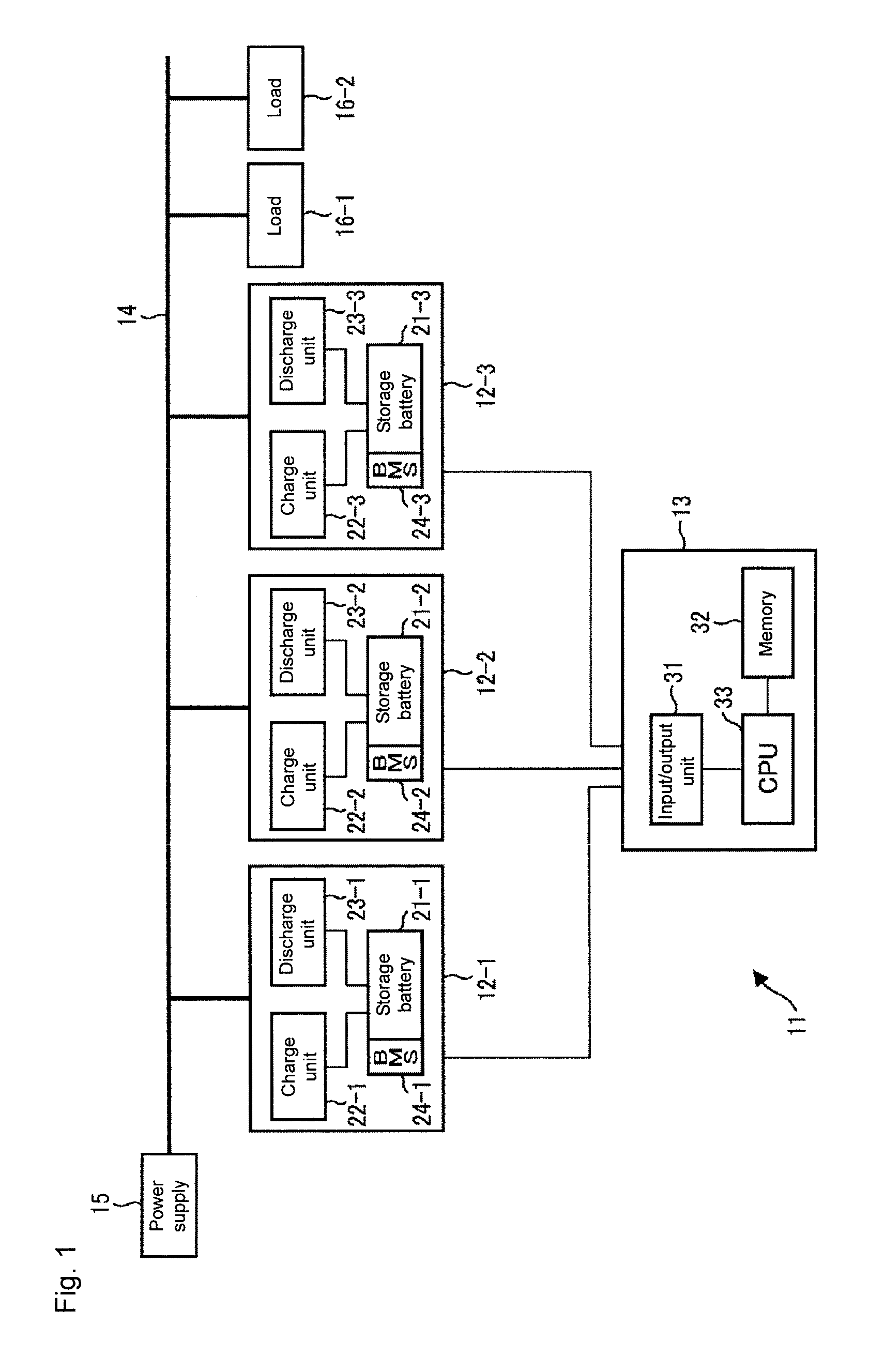
[0029]FIG. 1 is a block diagram illustrating a configuration example of an electricity storage system to which the technology of the disclosure is applied.

[0030]Referring to FIG. 1, electricity storage system 11 includes three electricity storage devices 12-1 to 12-3 and control device 13. In the configuration of the power supply system including electricity storage system 11, power supply 15 that supplies power through a power system and loads 16-1 and 16-2 that consume the power are connected to each other via power wiring 14 through which the power is transmitted to electricity storage system 11. Power supply 15 includes a DC power supply in which such natural energy as sunlight and wind power is used and an AC power supply, such as a commercial power supply, which supplies the power via the power system.

[0031]Electricity storage devices 12-1 to 12-3 are connected to loads 16-1 and 16-2 via power wiring 14 while connected to power supply 15 in parallel via power wiring 14. Elect...

second embodiment

[0167]FIG. 13 is a block diagram illustrating a configuration example of an electricity storage system to which the technology of the disclosure is applied.

[0168]In electricity storage system 11′ of FIG. 13, the same component as a component in electricity storage system 11 in FIG. 1 is designated by the same symbol, and the detailed description is neglected. Electricity storage system 11′ includes storage batteries 21-1 to 21-3 and battery management systems 24-1 to 24-3, and electricity storage system 11′ is identical to electricity storage system 11 in FIG. 1 in that power supply 15 and loads 16-1 and 16-2 are connected to each other via power wiring 14.

[0169]However, electricity storage system 11′ differs from electricity storage system 11 in FIG. 1 in that electricity storage system 11′ includes power conditioners 51-1 to 51-3, that power conditioners 51-1 to 51-3 include controllers 52-1 to 52-3, and that storage batteries 21-1 to 21-3 are connected to power wiring 14 via pow...


PUM


Abstract

The present disclosure relates to a storage battery control device that can exert better performance in a configuration in which a plurality of storage batteries are connected, a storage battery control method, a program, an electricity storage system, and a power supply system. A charge order table previously set according to a state of charge and a charge/discharge frequency of a storage battery that stores power is referred to, and based on the states of charge and the charge/discharge frequencies acquired from the storage battery provided in plural, a discharge order based on which discharge is preferentially performed with respect to the plurality of storage batteries is decided. In order to supply necessary power necessary to be output upon a request from a load, discharge power output from each of the plurality of storage batteries is set based on the decided discharge order.

Description

TECHNICAL FIELD[0001]The present disclosure relates to a storage battery control device, a storage battery control method, a program, an electricity storage system, and a power supply system, particularly to a storage battery control device that can exert better performance in a configuration in which a plurality of storage batteries are connected, a storage battery control method, a program, an electricity storage system, and a power supply system.BACKGROUND ART[0002]Conventionally, an electricity storage system to which a plurality of storage batteries are connected is used to obtain a prescribed capacity that cannot be obtained by one storage battery. Performance of the electricity storage system depends on a method for controlling a charge or a discharge of each storage battery.[0003]For example, Patent Document 1 discloses a technology in which, in a power supply system including a solar cell and a plurality of inverters, an inverter acting as a master unit controls operation a...

Claims


Application Information

Patent Timeline
IPC IPC(8): H02J7/00
CPCH02J2007/0067H02J7/0063H02J7/0013H02J7/0022H01M10/482H02J7/35H02J7/00H01M10/441H02J7/0025Y02E60/10
Inventor OHASHI, MAKOTONISHIKAWA, TAKEOSUNAHATA, YOSHINORIYAMADA, JUNICHIROOKADA, WATARU
Owner ORMON CORP
Why Eureka
Try Eureka