Method of controlling a switching converter in burst mode and related controller for a switching converter

a switching converter and burst mode technology, applied in the direction of electric variable regulation, process and machine control, instruments, etc., can solve the problems of affecting the efficiency of the switching converter, the output voltage or current ripple is out, and the switching converter is extremely selective and therefore expensiv

Active Publication Date: 2015-01-01
STMICROELECTRONICS INT NV
View PDF2 Cites 24 Cited by
  • Summary
  • Abstract
  • Description
  • Claims
  • Application Information

AI Technical Summary

Benefits of technology

[0022]In the method of this disclosure, this excellent result is obtained by sensing the difference between the error signal and the burst-stop threshold at the beginning of a burst period and, if the error signal has surpassed (either upwards or downwards) the burst-stop threshold, by setting the switching stage in a high impedance state at the occurrence of a new active edge of a clock signal, i.e., at the beginning of a first switching cycle to be skipped, keeping the switching stage in the high impedance state for an integer number of cycles of the clock signal, the integer number being determined upon the difference between the error signal and the burst-stop threshold, and re-enabling the switching stage to switch the energy tank circuit up to the end of the burst period.

Problems solved by technology

Switching converters show good performances when heavy loads are supplied, though their efficiency worsens when light loads are supplied, unless they are not properly managed.
This functioning mode causes a ripple of the output voltage or current Σout that may be reduced using an extremely selective (and thus expensive) low-pass filter LPF.
Moreover, very often the burst frequency Fburst is comprised in the range of acoustic frequencies, and thus may cause audible noise.

Method used


Image

  • Method of controlling a switching converter in burst mode and related controller for a switching converter
  • Method of controlling a switching converter in burst mode and related controller for a switching converter
  • Method of controlling a switching converter in burst mode and related controller for a switching converter

Examples


Embodiment Construction

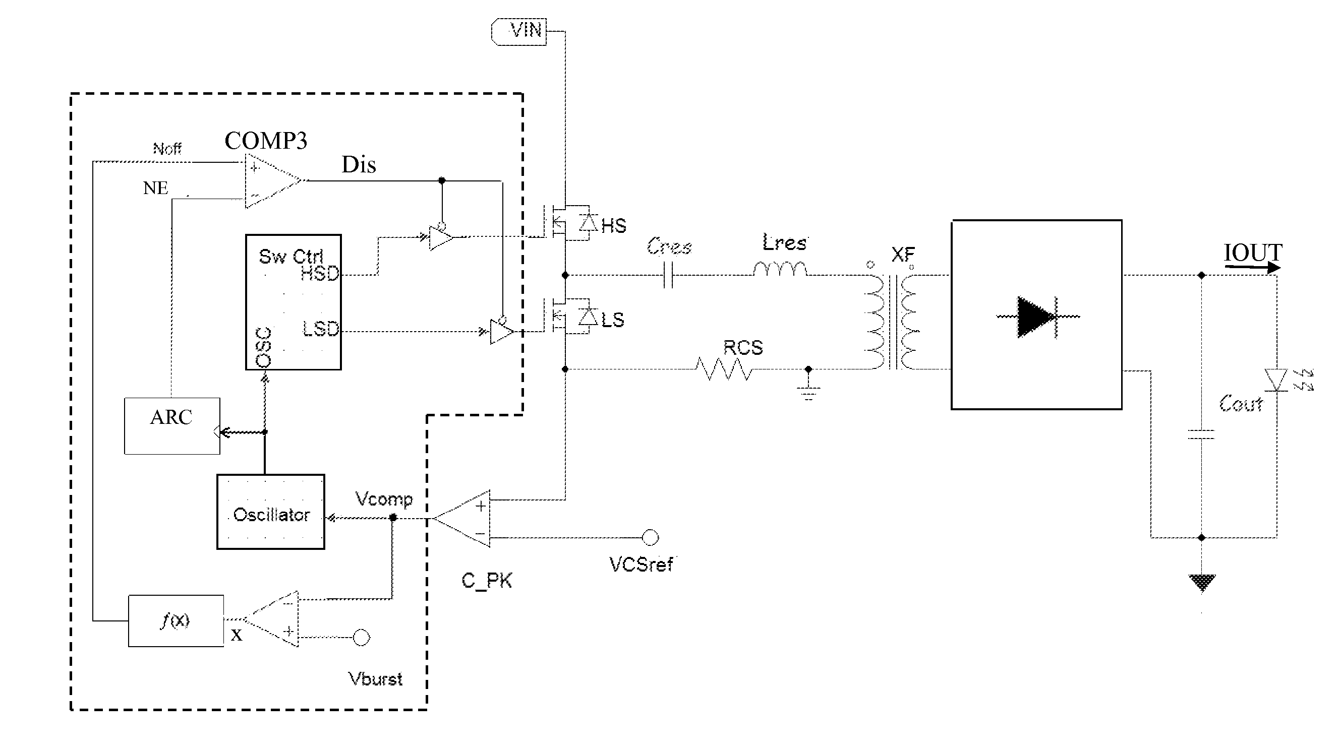
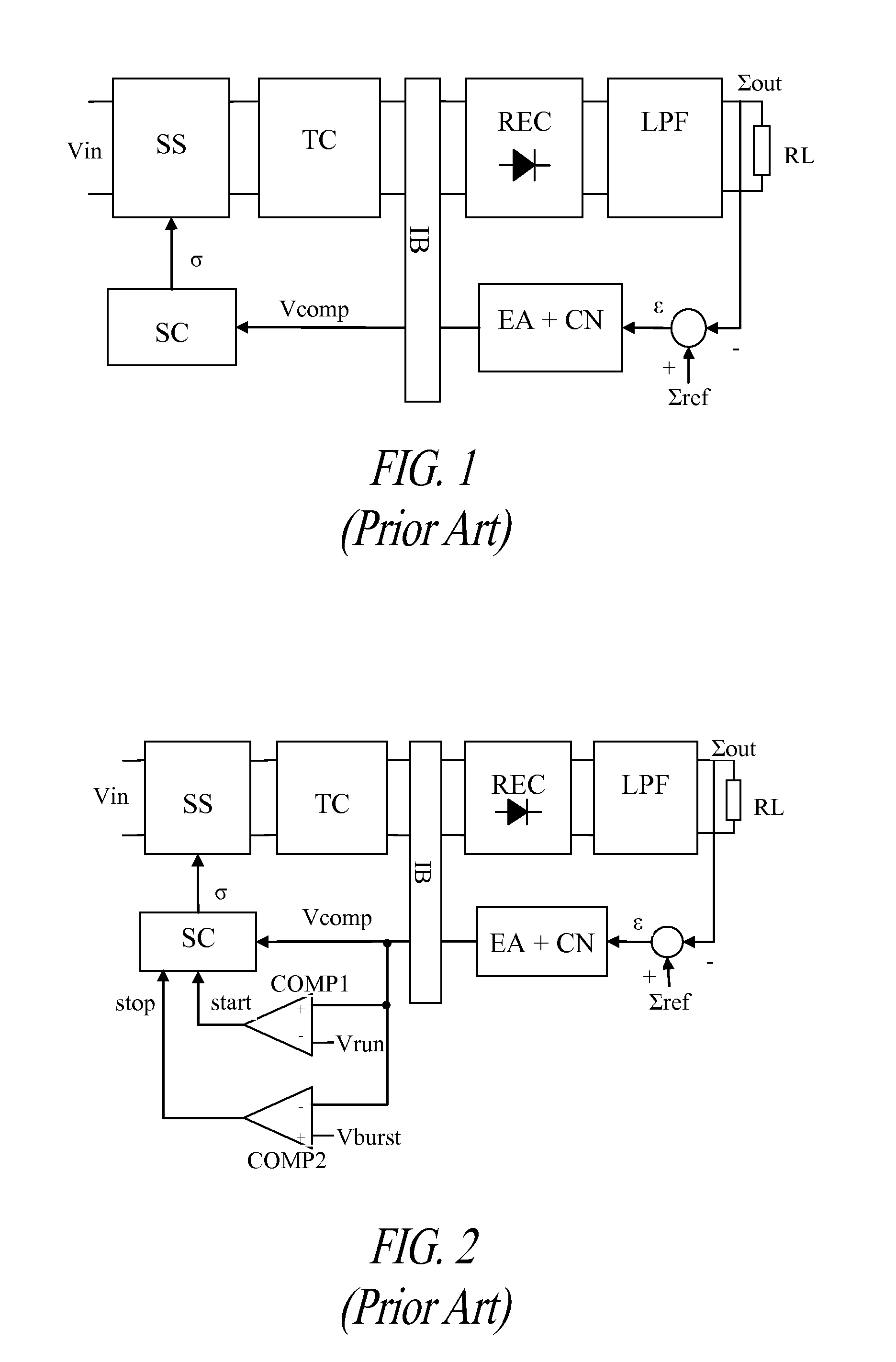
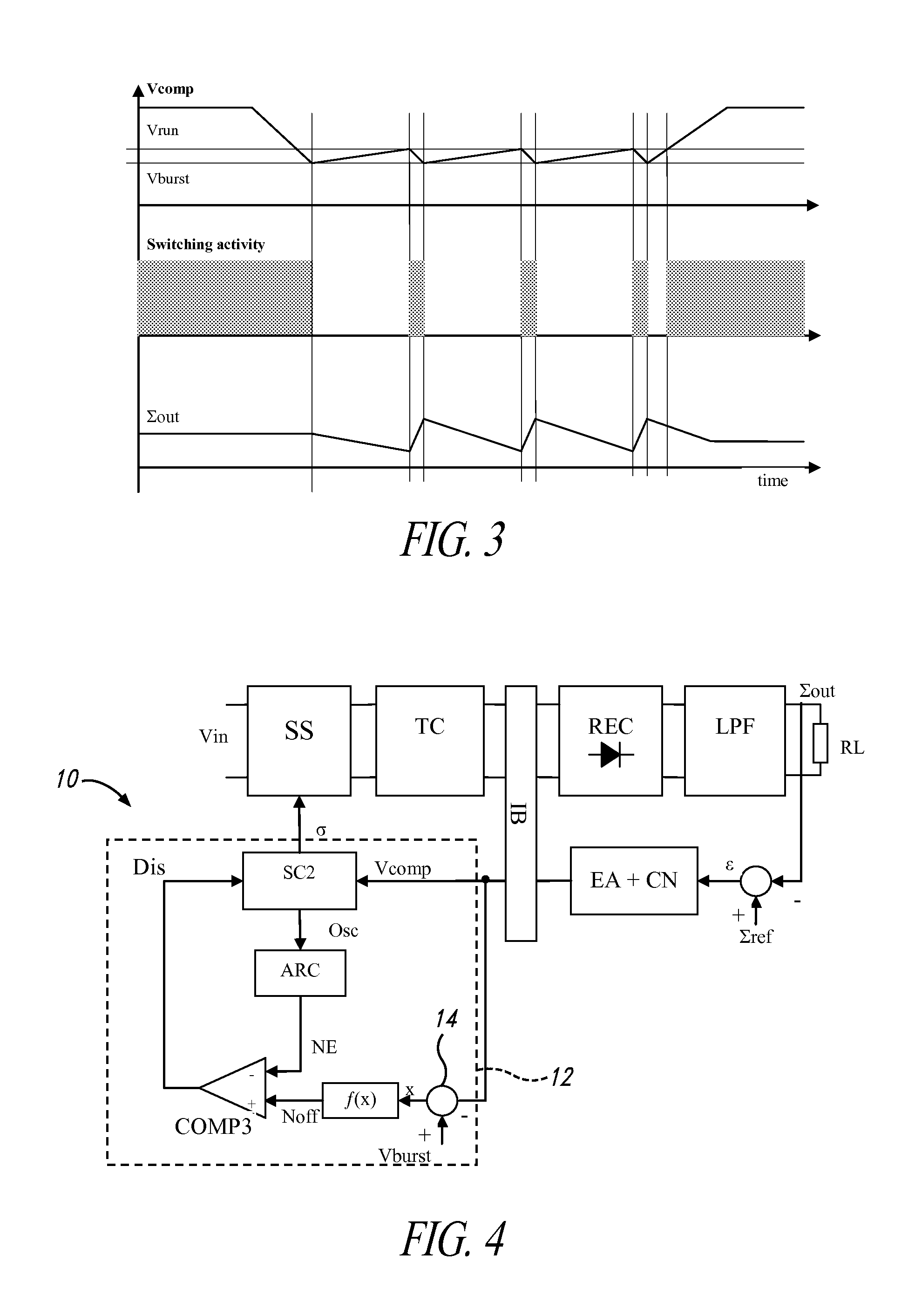
[0037]A high-level scheme of an embodiment of a switching converter 10 according to this disclosure is depicted in FIG. 4, in which the same blocks and signals have the same name. The controller 12 of the converter 10, within the dashed perimeter, includes an adder 14 that generates the difference x between the burst-stop threshold Vburst and the error signal Vcomp, a block f(x) receiving in input the difference x and generating a signal Noff representing an integer number corresponding to the difference x, a counter ARC counting cycles of a clock signal Osc that determines the switching cycles of the switching stage when in operation, and a comparator COMP3 generating a logic flag for enabling a switch controller SC2 that generates, when enabled, the control signal Σ for the switching stage SS. The switch controller SC2 of FIG. 4 differs from the switch controller SC of FIGS. 1 and 2 because it is configured to set the switching stage SS in a high impedance state when an active edg...


PUM


Abstract

A method of controlling a switching converter and a related controller suitable for the switching converter allow to implement a burst-mode functioning without generating acoustic noise and with a relevantly reduced ripple of the regulated DC voltage or current provided in output to a supplied load. The method includes sensing the difference between the error signal and the burst-stop threshold at the beginning of a burst period. If the error signal has surpassed (either upwards or downwards) the burst-stop threshold, the method sets the switching stage in a high impedance state at a new active edge of a clock signal, keeps the switching stage in the high impedance state for an integer number of cycles of the clock signal, and re-enables the switching stage to switch the energy tank circuit up to the end of the burst period. The integer number is determined based on the difference between the error signal and the burst-stop threshold,

Description

BACKGROUND[0001]1. Technical Field[0002]This disclosure relates to switching converters and more particularly to a method of controlling a switching converter in burst mode, a controller for implementing the method and a related switching converter.[0003]2. Description of the Related Art[0004]Switching converters are widely used in the field of power supply devices because of their performances in supplying high loads with a regulated voltage or current.[0005]They are characterized by a high switching frequency and, for reducing potentially large periodic losses at turn ON and OFF of the switches, numerous converters use a resonant tank circuit to reduce switching losses through zero-voltage switching or zero-current switching techniques.[0006]A basic fed-back architecture of a switching converter is depicted in FIG. 1. It has a forward path and a feedback path, the forward path comprising:[0007]a switching stage SS receiving in input an unregulated voltage VIN,[0008]an energy tank ...

Claims


Application Information

Patent Timeline
Patent Type & Authority Applications(United States)
IPC IPC(8): H02M3/335H02M1/00
CPCH02M3/33546H02M2001/0035H02M2001/0054H02M3/335H02M1/15Y02B70/16Y02B70/10H02M1/0035H02M1/0054
Inventor FERRAZZA, FRANCESCOD'ADDA, AMBROGIO GIUSEPPEADRAGNA, CLAUDIO
Owner STMICROELECTRONICS INT NV
Why Eureka
Try Eureka