Supercharge Your Innovation With Domain-Expert AI Agents!

Rectifying apparatus

a technology of rectifying apparatus and rectifying device, which is applied in the direction of climate sustainability, power electronics conversion efficiency, emergency protective circuit arrangement, etc., can solve the problems of backflow, reducing the efficiency of the rectifying apparatus, and the rectification apparatus cannot achieve rectification

Active Publication Date: 2015-01-01
KK TOSHIBA
View PDF23 Cites 2 Cited by
  • Summary
  • Abstract
  • Description
  • Claims
  • Application Information

AI Technical Summary

Benefits of technology

The first embodiment of the rectifying apparatus described in the patent has three main benefits. Firstly, it is more efficient in its operation. Secondly, it prevents any backflow from the output terminal.

Problems solved by technology

A conventional synchronous rectifying apparatus has a problem that, if the on-resistance is decreased in order to reduce loss, the rectifying apparatus can hardly achieve rectification, and a backflow occurs.
In the case of the conventional rectifying apparatus, however, a current flows because of a parasitic element of the pMOS transistor, and the efficiency of the rectifying apparatus decreases.

Method used


Image

  • Rectifying apparatus
  • Rectifying apparatus
  • Rectifying apparatus

Examples


first embodiment

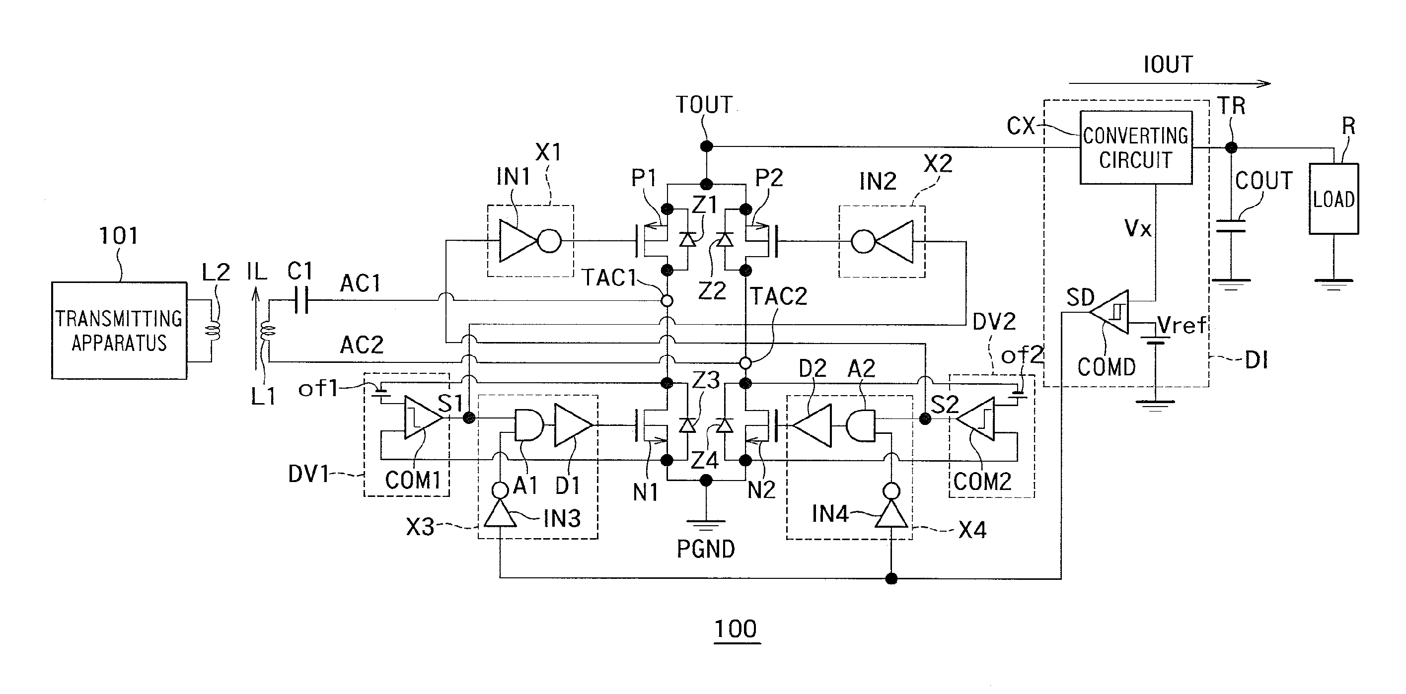
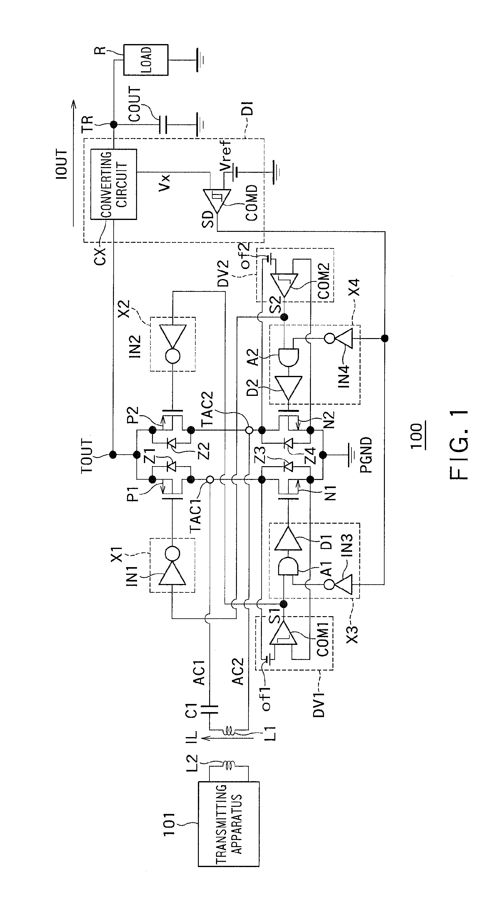
[0015]FIG. 1 is a circuit diagram showing an example of a configuration of a rectifying apparatus 100 according to a first embodiment.

[0016]In FIG. 1, a power transmitting apparatus 101 is configured to transmit electric power. The power transmitting apparatus 101 is a charger for mobile equipment, such as a smartphone and a tablet PC, for example.

[0017]A rectifying apparatus (power receiving apparatus) 100 is configured to receive electric power output from the power transmitting apparatus 101. The rectifying apparatus 100 is mobile equipment, such as a battery, a smartphone incorporating a battery and a tablet PC, or equipment for a battery charger connected to the equipment. The rectifying apparatus (power receiving apparatus) 100 may be any other equipment that receives electric power output from the associated power transmitting apparatus 101, including a rechargeable electric car, a household appliance and a product for underwater application.

[0018]Power transmission from the ...

second embodiment

[0093]FIG. 5 is a circuit diagram showing an example of a configuration of a rectifying apparatus 200 according to a second embodiment. In FIG. 5, the same reference symbols as those in FIG. 1 denote the same components as those in the first embodiment, and descriptions of those components will be omitted.

[0094]As shown in FIG. 5, the first voltage detecting circuit “DV1” has the first direct-current power supply “of1”, a third direct-current power supply “of3”, the first comparator “COM1” and a third comparator “COM3”. That is, the first voltage detecting circuit “DV1” in the second embodiment differs from the first voltage detecting circuit “DV1” in the first embodiment in that it further has the third direct-current power supply “of3” and the third comparator “COM3”.

[0095]The first direct-current power supply “of1” is connected to the first power receiving terminal “TAC1” at the negative electrode thereof.

[0096]The first comparator “COM1” compares the first voltage at the positiv...


PUM


Abstract

A rectifying apparatus (power receiving apparatus) 100 is configured to receive electric power output from the power transmitting apparatus 101. The rectifying apparatus 100 is mobile equipment, such as a battery, a smartphone incorporating a battery and a tablet PC, or equipment for a battery charger connected to the equipment. The rectifying apparatus (power receiving apparatus) 100 may be any other equipment that receives electric power output from the associated power transmitting apparatus 101, including a rechargeable electric car, a household appliance and a product for underwater application.

Description

CROSS-REFERENCE TO RELATED APPLICATION[0001]This application is based upon and claims the benefit of priority from the prior Japanese Patent Application No. 2013-134096, filed on Jun. 26, 2013, the entire contents of which are incorporated herein by reference.BACKGROUND[0002]1. Field[0003]Embodiments described herein relate generally to a rectifying apparatus.[0004]2. Background Art[0005]A conventional synchronous rectifying apparatus has a problem that, if the on-resistance is decreased in order to reduce loss, the rectifying apparatus can hardly achieve rectification, and a backflow occurs. As a measure against the backflow, a pMOS transistor on the high side can be forced to serve as a diode. In the case of the conventional rectifying apparatus, however, a current flows because of a parasitic element of the pMOS transistor, and the efficiency of the rectifying apparatus decreases.BRIEF DESCRIPTION OF THE DRAWINGS[0006]FIG. 1 is a circuit diagram showing an example of a configurat...

Claims


Application Information

Patent Timeline
IPC IPC(8): H02M7/217H02H7/12H02M7/12
CPCH02M7/217H02M2007/2195H02M7/219H02J2207/20H02J7/00712H02M7/2195H02J50/12Y02B70/10
Inventor OTSUKA, MASAFUMIAIZAWA, HIROTOSHITAKAYAMA, TORU
Owner KK TOSHIBA
Features
  • R&D
  • Intellectual Property
  • Life Sciences
  • Materials
  • Tech Scout
  • Unparalleled Data Quality
  • Higher Quality Content
  • 60% Fewer Hallucinations
Learn More