Sensor device

Inactive Publication Date: 2015-01-01
ORMON CORP
View PDF7 Cites 44 Cited by
  • Summary
  • Abstract
  • Description
  • Claims
  • Application Information

AI Technical Summary

Benefits of technology

[0017]One or more embodiments of the present invention provides a microphone which can make compatible both of (1) that a sound hole of a package is directly connected to

Problems solved by technology

However, in the microphone 11 adopting the structure illustrated in FIG. 1A, an internal space of the acoustic sensor 13 is a back chamber, and therefore the volume of the back chamber is limited and cannot be increased so much.
However, in the microphones disclosed in Patent Documents 1 and 2, the two acoustic sensors are arranged in a bottom surface of a package and a sound hole is opened in an upper surface of the package, and therefore the sound hole of the package cannot be directly connected to the acoustic sensors.
There is a concern that, when the two acoustic sensors are integrated, vibration of a diaphragm of one acoustic sensor is transmitted to the other acoustic sensor through the substrate, and the acoustic sensors interfere with each other and cause noise.
Further, in case where the two acoustic sensors are provided on one substrate, only when the two acoustic sensors both normally function, the acoustic sensors can

Method used


Image

  • Sensor device
  • Sensor device
  • Sensor device

Examples


first embodiment

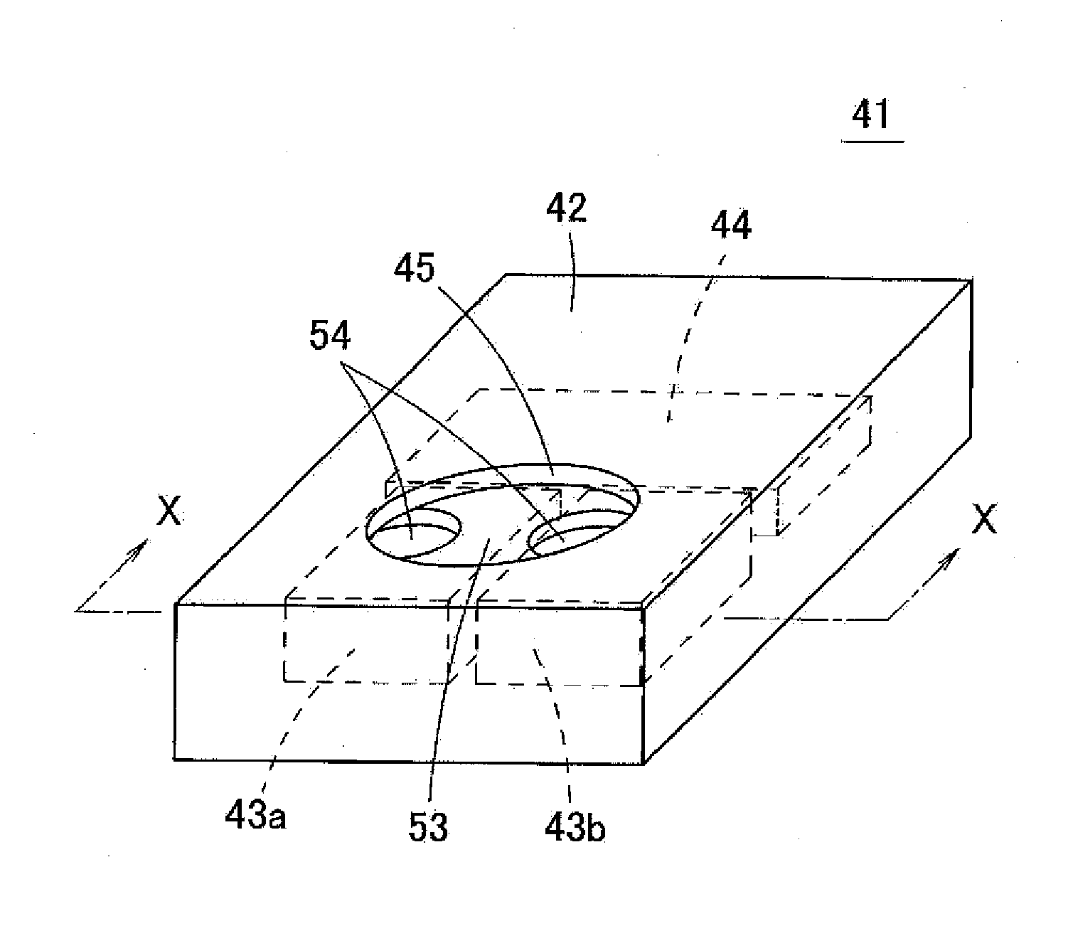
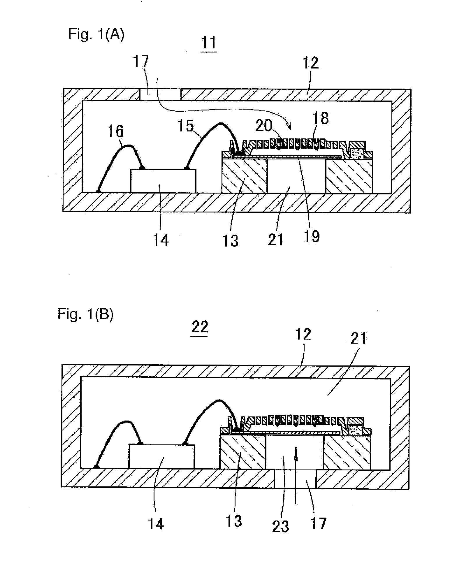
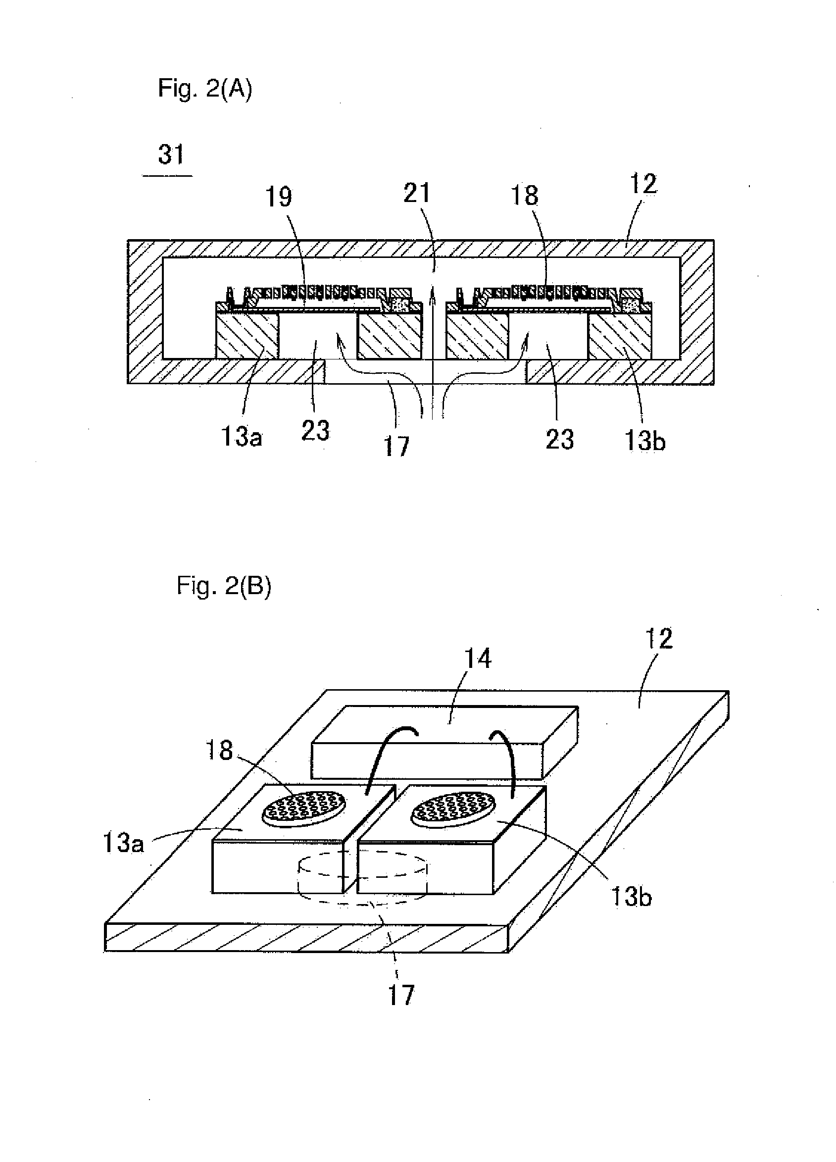
[0047]A microphone of the first embodiment of the present invention will be described below with reference to FIGS. 4 to 6. FIG. 4 is a perspective view illustrating a microphone 41 of the first embodiment of the present invention when seen from a lower surface side. FIG. 5A is an X-X line cross-sectional view in FIG. 4, and FIG. 5B is a perspective view illustrating an inside of a package of the microphone 41. FIG. 6 is a perspective view illustrating a sound hole 45 of a package 42 and an interposer 53 (support base).

[0048]As illustrated in FIGS. 5A and 5B, in the microphone 41, two acoustic sensors 43a and 43b and a processing circuit 44 such as an ASIC are accommodated in the package 42, and the acoustic sensors 43a and 43b and the processing circuit 44 are connected by bonding wires. The flat interposer 53 is fixed to a bottom surface of the package 42, and the acoustic sensors 43a and 43b are fixed to the upper surface of the interposer 53 and close to each other without conta...

modified example 1

[0065]FIG. 7 is a cross-sectional view illustrating a microphone of a modified example of the first embodiment of the present invention. In this modified example, an opening area of a sound hole 45 is made larger. Particularly, the opening area of the sound hole 45 is made larger such that penetration holes 54 and 54 of the interposer 53 are both accommodated in the sound hole 45 when seen from a direction vertical to an upper surface of an interposer 53.

[0066]In a microphone 41 of the first embodiment, the strength of a package 42 is enhanced by adhering the interposer 53 to the bottom surface of the package 42, so that it is possible to keep the strength of the package 42 even when the opening area of the sound hole 45 is made larger. Further, the interposer 53 is interposed between acoustic sensors 43a and 43b and the package 42, so that it is possible to independently determine the size of each of the acoustic sensors 43a and 43b and the opening area of the sound hole 45. Conseq...

modified example 2

[0067]Three or more acoustic sensors may be built in a microphone. FIG. 8A is a perspective view illustrating an inside of a package of a microphone of a modified example of the first embodiment of the present invention. FIG. 8B is a perspective view illustrating a sound hole of the package and an interposer in the microphone in FIG. 8A.

[0068]According to this modified example, four acoustic sensors 43a, 43b, 43c and 43d are built in a package 42. In an interposer 53, four penetration holes 54 are opened to meet positions of cavities (front chambers 52) of the acoustic sensors 43a to 43d. Further, a sound hole 45 is opened in the bottom surface of the package 42 such that at least part of the four penetration holes 54 overlap when seen from a direction vertical to the upper surface of the interposer 53.

[0069]Even when three or more acoustic sensors are built in, it is possible to possible to provide the same function and operation as those of the microphone 41 by making the other co...


PUM


Abstract

A microphone has a package, a support base fixed to an inner surface of the package, and a plurality of acoustic sensors disposed on a surface of the support base. The package has a sound hole opened in a region in which the support base is disposed. The support base has penetration holes that include a plurality of openings opened in the surface of the support base and that have the sound hole and a cavity in each of the acoustic sensors in communication with each other. The openings of the penetration holes in the surface of the support base are spaced apart from each other, and are in communication with the cavity of each of the different acoustic sensors.

Description

BACKGROUND[0001]1. Technical Field[0002]The present invention relates to a microphone having a plurality of built-in acoustic sensors.[0003]2. Related Art[0004]FIG. 1A is a schematic cross-sectional view illustrating a structure of a general microphone. In this microphone 11, an acoustic sensor 13 (sensor chip) and a processing circuit 14 are mounted on a bottom surface of a package 12. The acoustic sensor 13 and the processing circuit 14 are connected by a bonding wire 15, and the processing circuit 14 is connected to a circuit pattern in the package 12 by a bonding wire 16. Further, a sound hole 17 is opened in an upper surface of the package 12.[0005]In the microphone 11 adopting the structure illustrated in FIG. 1A, acoustic vibration is introduced from the sound hole 17 into the package 12 (a direction in which the acoustic vibration is transmitted is indicated by an arrow in FIG. 1A. The same applies to the following drawings). This acoustic vibration enters the acoustic senso...

Claims


Application Information

Patent Timeline
IPC IPC(8): H04R1/08
CPCH04R1/08B81B7/0061B81B2201/0257H04R1/245H04R1/2807H04R19/005H04R19/04H04R2201/401H04R2410/03H01L2224/48091H01L2224/48137H01L2924/15151H01L2924/16151H01L2924/00014
Inventor KASAI, TAKASHI
Owner ORMON CORP
Why Eureka
Try Eureka