Rasp holder fitted with a handle

a technology of a handle and a holder is applied in the field of forming a tool holder, which can solve the problems of wear and tear of the device, and achieve the effects of reducing wear and tear, and being resistant to stress and for

Inactive Publication Date: 2015-01-01
XNOV IP
View PDF1 Cites 7 Cited by
  • Summary
  • Abstract
  • Description
  • Claims
  • Application Information

AI Technical Summary

Benefits of technology

[0005]The aim of the present invention is to overcome the disadvantages of the prior art by proposing a tool holder, in particular a milling cutter holder, which on the one hand has a simple structure, in particular simpler than those of the milling cutter holders of the prior art, and which on the other hand has greater longevity, being more resistant to the stresses and forces associated with the action of the rasp and the drive of the motor.

Problems solved by technology

As a result not only do these devices have a complex structure but they also wear out quickly.

Method used


Image

  • Rasp holder fitted with a handle
  • Rasp holder fitted with a handle
  • Rasp holder fitted with a handle

Examples


Embodiment Construction

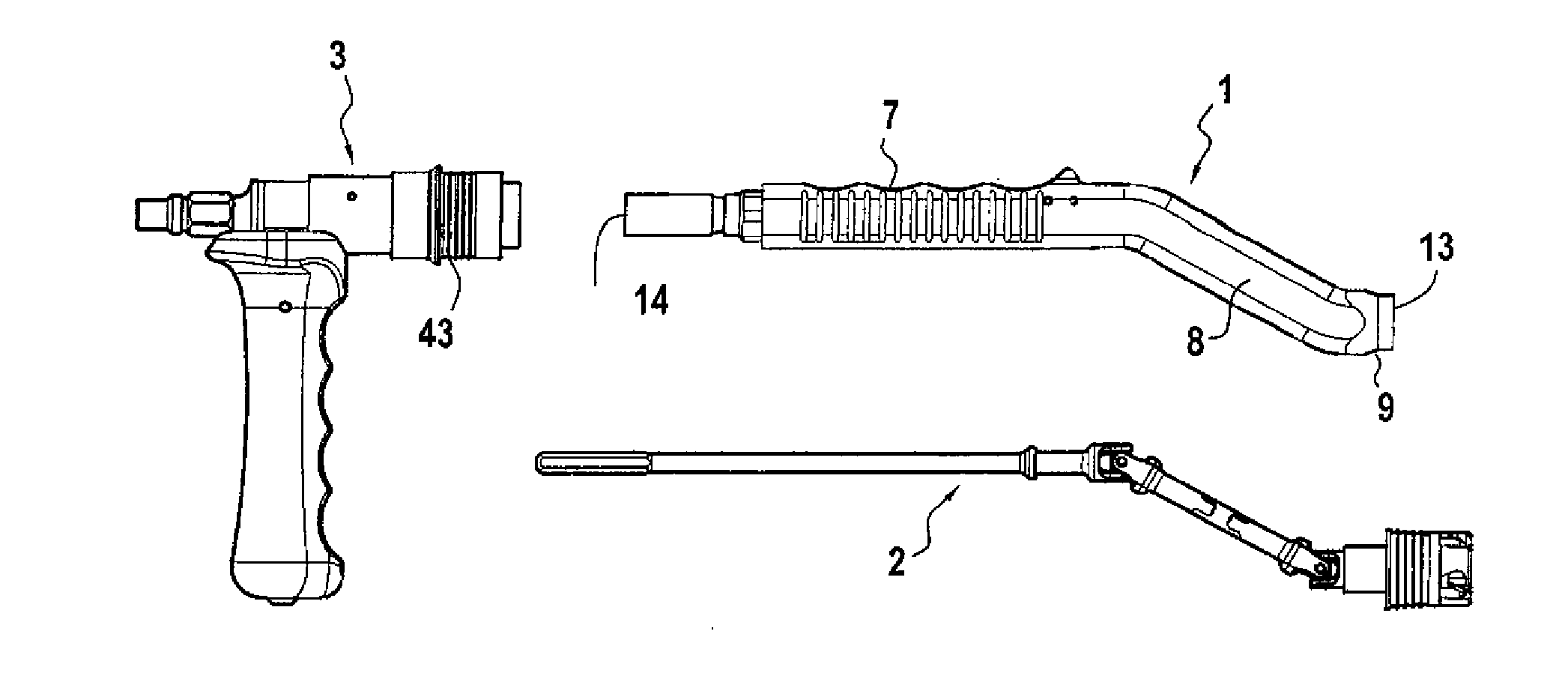
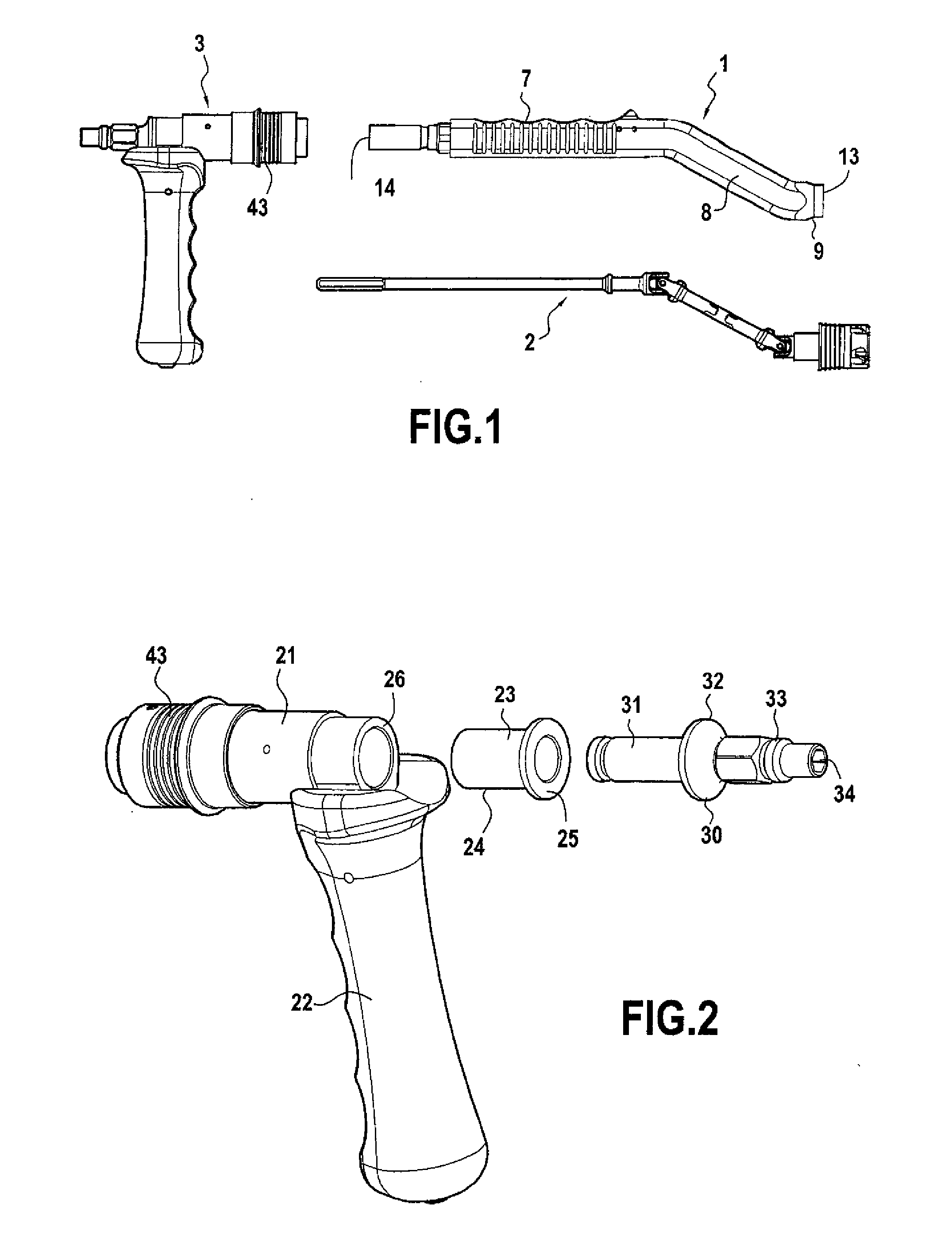
[0019]FIG. 1 shows three main parts of a rasp holder according to the invention, a main part 1 of the body, a transmission element 2 and an auxiliary part 3 supporting a gripping element 22 respectively. The two parts 1 and 2, the main part and auxiliary part, distal and proximal part respectively, form in a general manner the body of the device which receives the transmission 2.

[0020]The main part 1 is an oblong element with a substantially cylindrical shape with a substantially square cross section and formed by a wall 4 from above and two lateral walls, the three walls, the top one and lateral walls, defining between them an internal channel 5 to the bottom and being designed to receive the transmission 2. The main part 1 also comprises a lateral distal opening 13 and a distal opening 14.

[0021]At its proximal end, the main part is terminated by a proximal section 6 with a substantially circular cross section with a smaller dimension than the rest of the main body. The channel 5 c...


PUM


Abstract

Tool holder, in particular a milling cutter holder, which comprises a main body (1) with a substantially oblong cylindrical shape defining a channel in which a transmission (2) passes designed to transmit to the tool, in particular the milling cutter, a movement from the axis of a drive motor, and a gripping element (3) for gripping the tool holder, characterised in that an intermediate part (30) is provided arranged between the transmission (2) and the axis of the drive motor, the intermediate part comprising means for enabling the rotatable connection of said intermediate part to the transmission and the axis of the motor, the intermediate part comprising means (32) forming an abutment designed to lock in translation in the longitudinal direction of displacement of the axis of transmission by abutment in particular against the gripping element.

Description

TECHNICAL FIELD[0001]The present invention relates to a device forming a tool holder for cutting, rasping or removing bone, in particular a rasp holder or a milling cutter holder, in particular for rasping bone from a hip.BACKGROUND ART[0002]The tool holder, in particular the milling cutter holder, forms the interface between the tool, in particular the milling cutter, and a drive motor, in particular an electric motor, designed to drive the tool in rotation, in particular the milling cutter, in order to rasp the bone.[0003]Milling cutter holders of this kind are already known. They are formed by a hollow body with an oblong, substantially cylindrical shape, defining an internal channel through which a transmission rod passes designed to provide transmission between on the one hand the milling cutter arranged at a distal end of the milling cutter holder and on the other hand an axis of rotation of the motor at a proximal end opposite the distal end. The device also comprises an elem...

Claims


Application Information

Patent Timeline
Patent Type & Authority Applications(United States)
IPC IPC(8): A61B19/00A61B19/02A61B17/16
CPCA61B17/1659A61B19/26A61B19/0256A61B17/1622A61B17/1666A61B17/1633A61B17/1631
Inventor BIEGUN, JEAN-FRANCOIS
Owner XNOV IP
Why Eureka
Try Eureka