
Intraocular lens

a technology of intraocular lens and lens body, applied in intraocular lens, medical science, prosthesis, etc., can solve the problems of reducing the image resolution ability of the retina, affecting the intended vision function, and affecting the appearance of “tropia”

Active Publication Date: 2015-01-01
TELEON HLDG BV
View PDF0 Cites 22 Cited by
  • Summary
  • Abstract
  • Description
  • Claims
  • Application Information

AI Technical Summary

Benefits of technology

The patent aims to improve the visibility and field of view of patients who have macular translocation surgeries. These surgeries can cause the macula to move, leading to difficulty in aligning the patient's line of sight with the new macular location. The invention redirects the retinal image to the new macular location, reducing or correcting the "tropia" appearances and improving visual function.

Problems solved by technology

Peripheral retina has low receptors (cons and rods) densities, which gives rise to a relatively poor resolution ability.
They often have compromised fovea at the center of the macula.
The increased spacing leads to decreased image resolution ability of the retina.
Such telescopes are often mounted on spectacles, which are heavy and are not appealing cosmetically.
The main disadvantage of using a telescope system alone is the resultant narrow visual field of view and overall poor image quality, which could cause a safety concern during normal daily activities.
The prism does not magnify the retinal images and therefore, the problem of low visual resolution due to the larger peripheral retina receptor spacing is not resolved.
This visual aid is often used as a desk-mounted device, which limits the application range for patients.
A handheld version of this visual aid has vision instability and focus problems for patients with hand tremors.
Diffractive optics structures are inherently causing chromatic aberration and considerable halo's, glare and at loss of light energy of at least 20%, which reduces contrast sensitivity.
All known designs have disadvantages, for instance, providing halo's, loss of light, or loss of visual resolution.

Method used


Image

  • Intraocular lens
  • Intraocular lens
  • Intraocular lens

Examples


Embodiment Construction

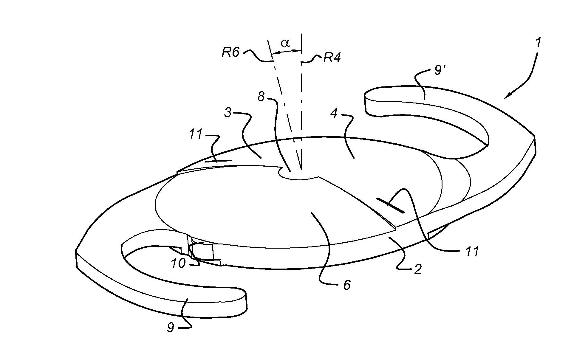
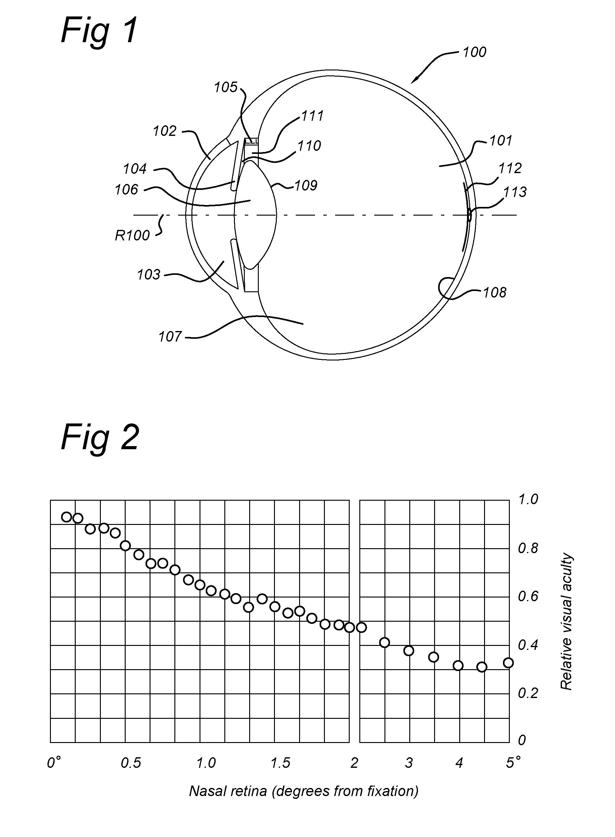
[0056]A schematic view of a human eye 100 with its natural lens 106 inside lens capsule or capsular bag 109 is shown in FIG. 1. The eye has a vitreous body 101 within posterior chamber 107. Retina 108 is on the inside of the posterior chamber 107, which further comprises macula 112 with fovea 113 at the centre thereof. The macula contains the photoreceptor cells, the fovea predominantly having cone photoreceptor cells although it does not have a sharply defined boundary. It merely shows a gradual transition from an area having a high density of (cone) photoreceptor cells to a peripheral area that predominantly has rod photoreceptor cells at decreasing density going from the center of the macula outwards. An optical axis R100 of eye 100 passes through the centre of iris 104 and the center of macula 112 and fovea 113. The eye further has a cornea 102 and an anterior chamber 103. The lens 106 and capsular bag 109 are held by ciliary muscle 105 and zonule fibres or ciliary zonules 111. ...


PUM


Abstract

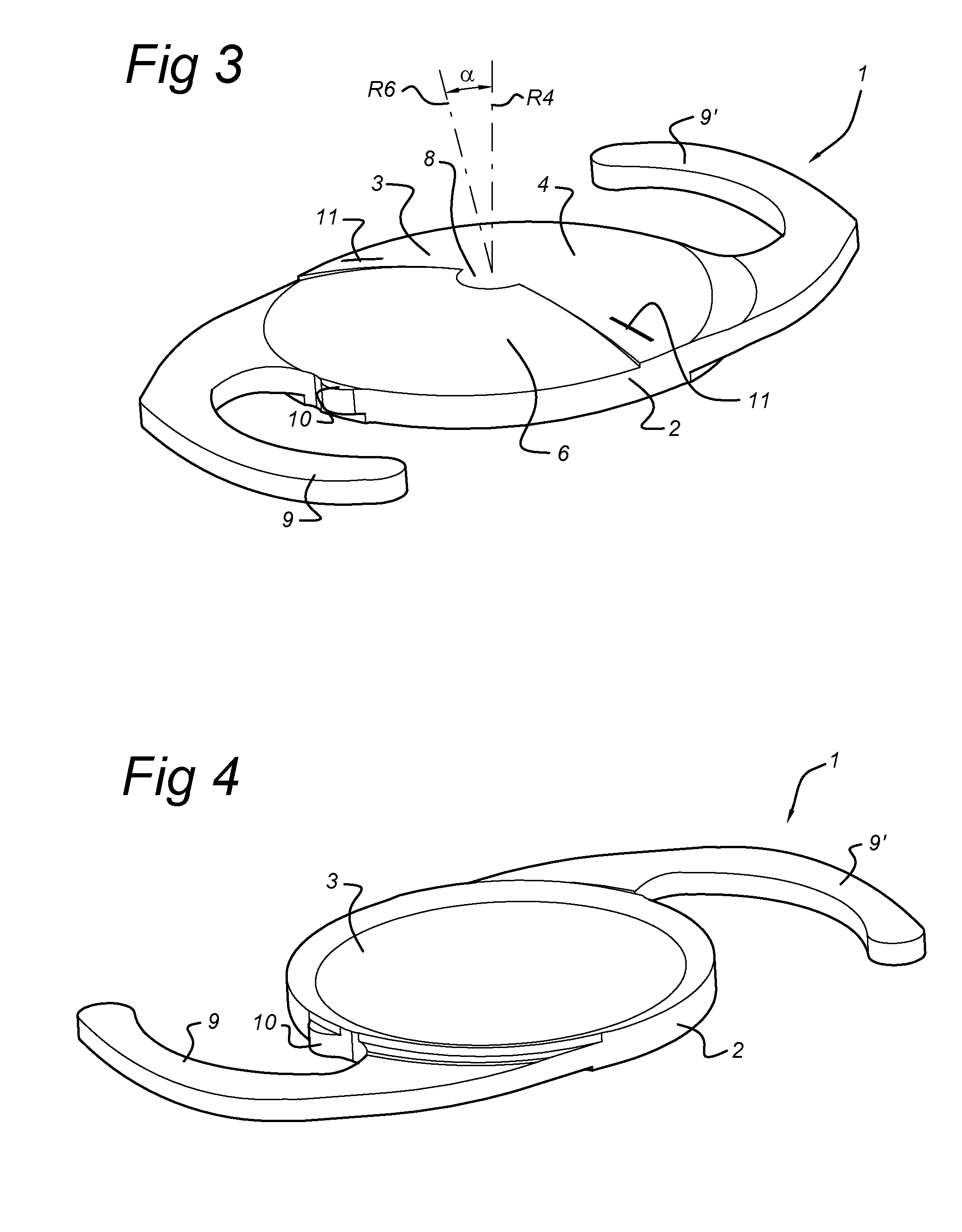
An intraocular lens includes an optic, which includes a first lens having a first optical axis for alignment with an optical axis of the human eye having a macula; and a second lens having a second optical axis. The second optical axis and the first optical axis enclose an angle between 0.5 and 10 degrees. The first and second lens are arranged next to one another in a direction transverse to the first optical axis to provide no overlap in a direction along the first optical axis such that the first lens and the second lens each, independent from one another, image onto the macula of the eye. The angle and a direction of the second optical axis are chosen such that the second lens images onto a functional part of the macula of the human eye, which functional part is not compromised by a defect, such as a scotoma.

Description

FIELD OF THE INVENTION[0001]The present invention relates to an intraocular lens comprising an optic, said optic comprising a first lens having a first optical axis for alignment with an optical axis of the human eye.BACKGROUND OF THE INVENTION[0002]Patients suffering from macula degeneration usually have impaired central visual fields and often rely heavily on peripheral vision, i.e. vision provided by the peripheral retina around the center of the macula, for daily tasks. Peripheral retina has low receptors (cons and rods) densities, which gives rise to a relatively poor resolution ability.[0003]Such patients suffering from (age-related) macular degeneration are usually generally referred to as AMD patients. They often have compromised fovea at the center of the macula. However, there are still functional retina receptors surrounding the compromised receptors. These functional retina receptors are often peripherally located and have a larger spacing between each other. The increas...

Claims


Application Information

Patent Timeline
IPC IPC(8): A61F2/16
CPCA61F2/1637A61F2/1648A61F2/1602A61F2250/0053A61F2002/1699
Inventor WANDERS, BERNARDUS, FRANCISCUS, MARIA
Owner TELEON HLDG BV
Learn More