Element Resistance Measurement in an Electricity Meter

Active Publication Date: 2015-01-01
LANDIS GYR LLC
View PDF7 Cites 39 Cited by
  • Summary
  • Abstract
  • Description
  • Claims
  • Application Information

AI Technical Summary

Benefits of technology

[0009]The present invention address the above described needs, as well as others by performing voltage measurements on one or both sides of a switch or other element at different times when the line current through the contact or element is different. Based on those

Problems solved by technology

There exists a potential for degradation of the switch contacts, particularly if the switches are used with some frequency.
Such resistance creates additional power loss within the meter, which is undesirable.
In particular, because of voltage drop across the contacts can be very small, and large common mode voltage, the tolerance of the measurement circuitry in some applications can cause significant errors in the contact resistance m

Method used


Image

  • Element Resistance Measurement in an Electricity Meter
  • Element Resistance Measurement in an Electricity Meter
  • Element Resistance Measurement in an Electricity Meter

Examples


Embodiment Construction

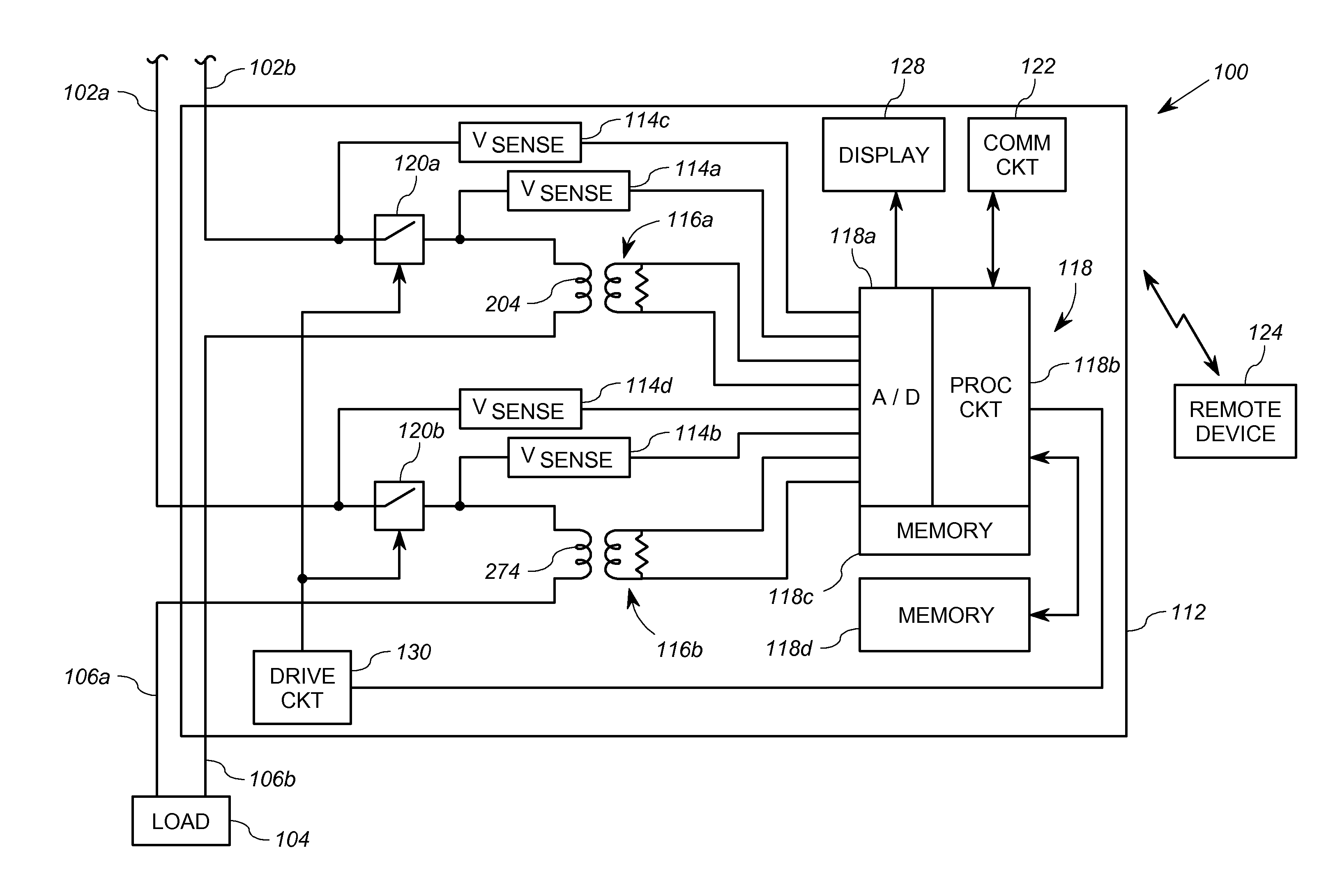
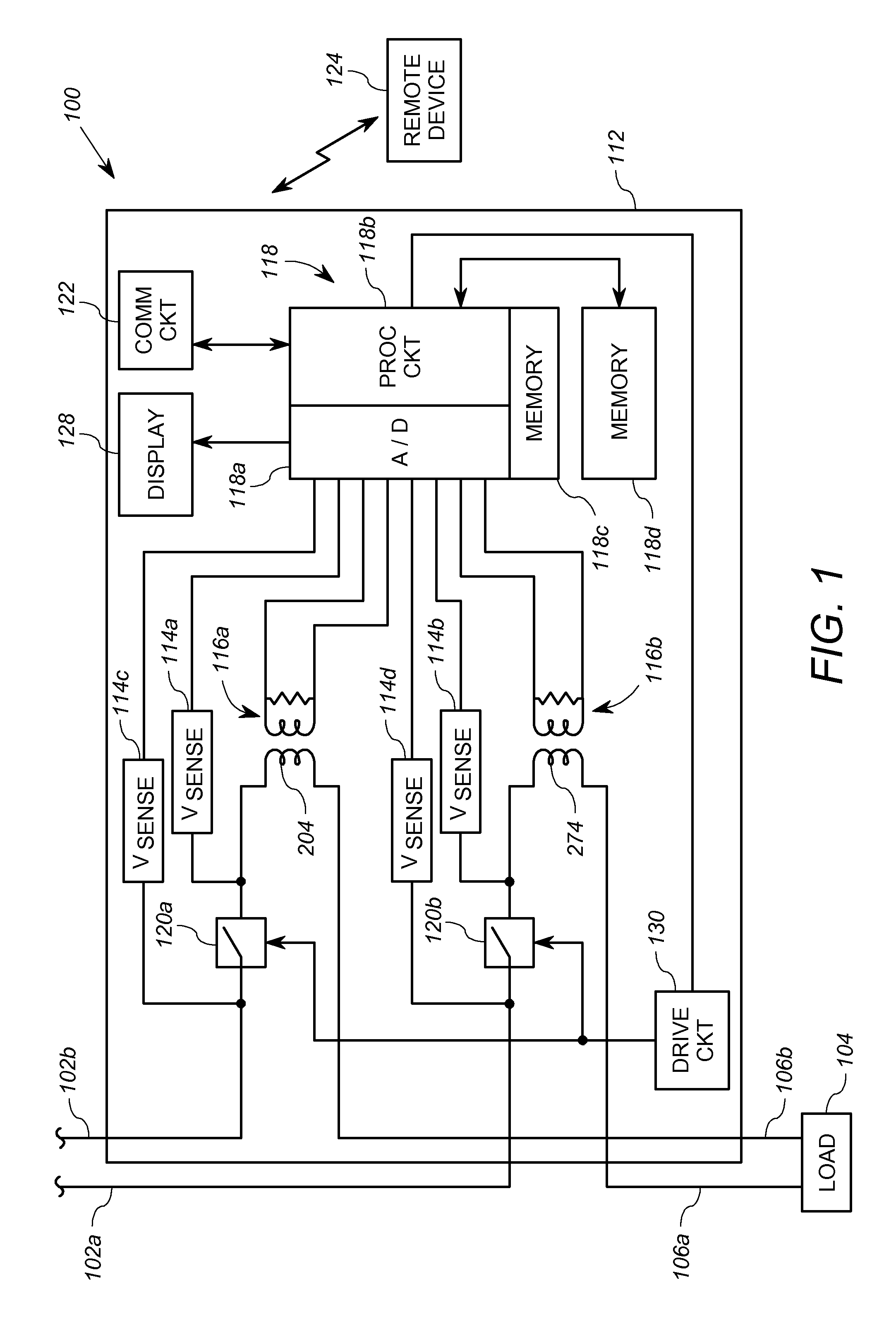
[0017]Referring now to the drawings, and more particularly to FIG. 1, a diagram of an electrical utility meter 100 constructed according to aspects of the present invention is shown. It will be appreciated that the one or more inventive aspects described herein may be implemented in many configurations of electricity meters, wherein the meter includes electrical elements in series with the AC line voltage, and is not limited to one having the specific architecture of the meter in FIG. 1.

[0018]In FIG. 1, the meter 100 is operably coupled to utility power lines 102a, 102b. The utility power lines 102a, 102b are connected to a source of electricity, such as a power transmission and distribution system, not shown. A load 104 (typically a consumer of electrical power) is connected to the power lines 102a, 102b through respective feeder lines 106a, 106b. The meter 100 is operably coupled at the intersection of the feeder lines 106a, 106b and the power lines 102a, 102b to detect the amount...


PUM


Abstract

A method measures a resistance of an element that is operably coupled to receive an AC line voltage. The method includes obtaining a first voltage measurement value V1A from a first side of the element at a first time, and obtaining a second voltage measurement value V2A from a second side of the element at the first time. The method also includes obtaining a first current measurement value IA through the element at the first time, and obtaining a second current measurement value IB through the element at the second time. The method further includes obtaining a third voltage measurement value V1B from the first side of the element at a second time, and obtaining a fourth voltage measurement value V2B from the second side of the element at the second time. The processing device determines the resistance at least in part based on the values V1A, V2A, V1B, V2B, IA and IB. The determination based on an adjusted difference of V2B and V2A.

Description

FIELD OF THE INVENTION[0001]The present invention relates generally to the field of electricity meters, and particularly to measurement of resistance of elements within the electricity meter.BACKGROUND[0002]Electricity meters that measure energy consumption or power consumption typically connect between a utility power line and a load. For example, an electricity meter for a residential customer is often connected at the point at which the electrical system of the residence connects to the utility line. The meter may thereby perform measurements regarding the energy consumed by the load.[0003]Utility meters often include one or more electrical contacts across which the load voltage and a significant amount of current may be found. For example, certain meters have switches that allow for controllable connection and disconnection of electrical service to the customer, i.e., the load. Such switches necessarily have substantial contacts to carry the entire customer load current, often i...

Claims


Application Information

Patent Timeline
IPC IPC(8): G01R27/14
CPCG01R27/14G01R27/205G01R31/3274
Inventor VOISINE, JOHN, T.
Owner LANDIS GYR LLC
Why Eureka
Try Eureka