Solar generator platform

Inactive Publication Date: 2015-01-08
POWERAK
View PDF6 Cites 15 Cited by
  • Summary
  • Abstract
  • Description
  • Claims
  • Application Information

AI Technical Summary

Benefits of technology

[0095]If the pipe adaptor is oriented [and fixed in the top part], so that in a single top part all the parallel pipe fixings are normal to each other, we can then assemble a substructure building block, that through the horizontally interlocked pipe array will impart the CP membrane vertical [z], and planar [x-y horizontal] strength. The pipe adaptor part has a number of locking [note: this mechanism is identical to the hinge part], cylinders on the faces normal to the pipe fixing direction. This is to secure the transverse pipe ends across the top parts. The complex pattern produced via the connection scheme, provides the interconnection and strength for each module to beco

Problems solved by technology

This system appears complex and time consuming to assemble.
Levels of maturity restrict these prior art devices specifically due to:Limited adaptation capability to large/unlimited practical scale payload carrying capacity and therefore little possibility of commercial utility level power generation potential;General wind stability issues;Specific wind stability issues with commercial water level changes on deployments du

Method used


Image

  • Solar generator platform
  • Solar generator platform
  • Solar generator platform

Examples


Example

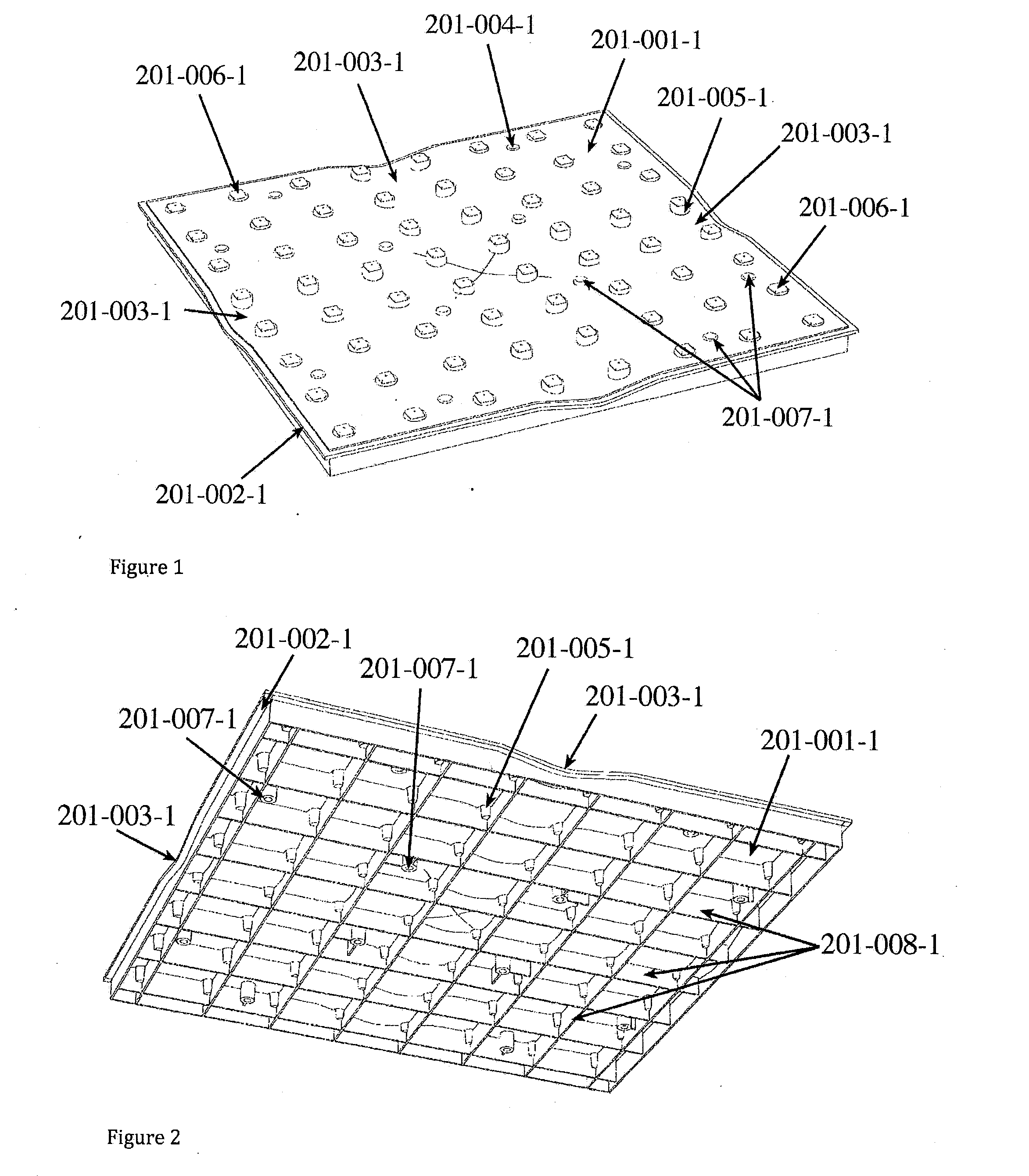
[0113]FIGS. 1 & 2 illustrate: the first embodiment deck with top and bottom views respectively;

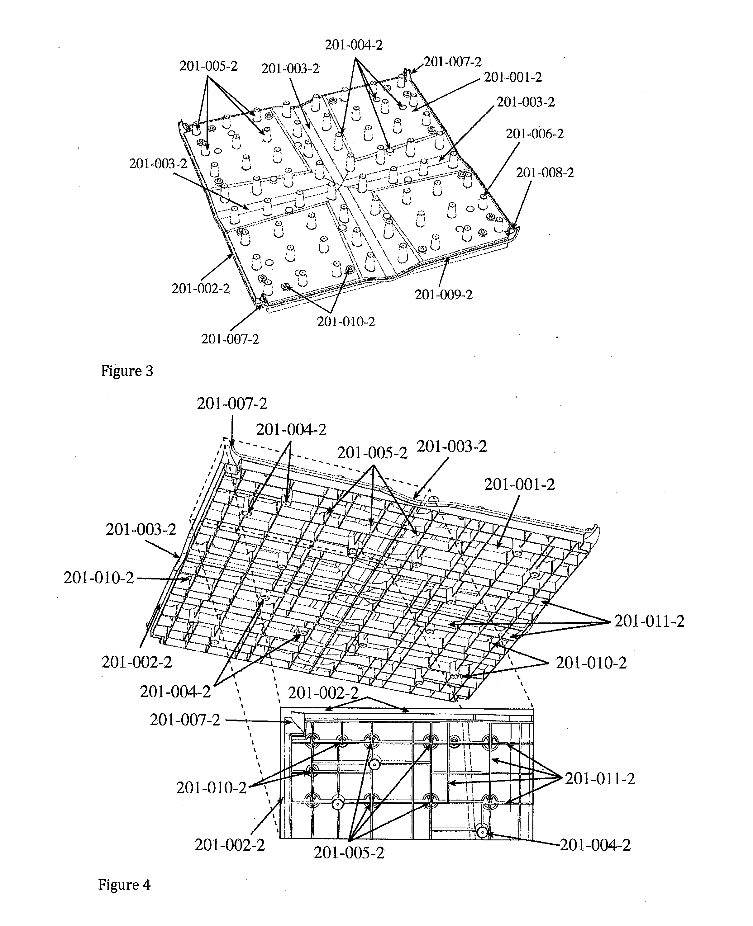
[0114]FIGS. 3 & 4 illustrate: the preferred deck embodiment with top and bottom views respectively;

[0115]FIGS. 5 & 6 illustrate: the first embodiment of the invert with top and bottom views respectively;

[0116]FIGS. 7 & 8 illustrate: the preferred embodiment of the invert with top and bottom views respectively;

[0117]FIG. 9 illustrates: the jointing detail of two preferred embodiment inverts;

[0118]FIG. 10 illustrates: an explosion view of the first embodiment deck and invert assembly;

[0119]FIG. 11 illustrates: an explosion view of the preferred embodiment deck and invert assembly;

[0120]FIG. 12 illustrates: a sectional view of the first embodiment of the deck and invert part assembly with floatation considerations;

[0121]FIG. 13 illustrates: a sectional view of the preferred embodiment of the deck and invert part assembly with floatation considerations;

[0122]FIG. 14 illustrates: the assembly l...

Example

[0123]FIG. 15 illustrates: a 4×4 sq invert with a 3×3 deck [second embodiment] assembly top view layout showing the connection of, and assembly scheme;

[0124]FIG. 16 illustrates: a bottom view of the first embodiment LHS invert moulding;

[0125]FIG. 17 illustrates: a top view of the preferred embodiment LHS square invert moulding;

[0126]FIG. 18 illustrates: the first embodiment seal ‘cross’ junction part;

[0127]FIG. 19 illustrates: the first embodiment synthetic rubber [typically: EPDM], flexible seal extrusion with an end sectional drawing;

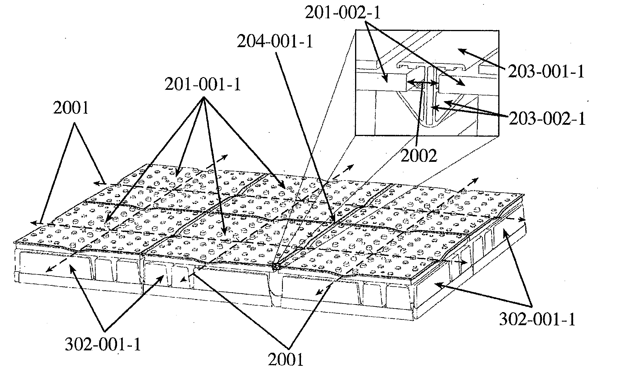
[0128]FIG. 20 illustrates: a 3×2 array of the first embodiment deck and invert with the inclusion of seals, seal junctions and left and right hand half invert parts. Including a magnified view of the installed seal;

[0129]FIG. 21 illustrates: the assembly layout of the preferred embodiment deck, invert and half invert treatment of ‘ragged edges’ in the deployment;

[0130]FIG. 22 illustrates: the preferred embodiment synthetic rubber flexible seal extrusi...

Example

[0224]The second deck embodiment also includes a further set of smaller perimeter extrusions [201-010-2, FIGS. 3, 4, 13, 25&26], for the purpose of the connection of a geo-membrane [Hypalon, CSPE or similar] skirt adaptor [203-001-2, FIG. 24], on the shoreline facing side of each deck, around the entire perimeter of the deployment. The skirt adaptor during assembly is pushed over the deck perimeter extrusion [201-002-2, FIG. 25], and the perimeter extrusion lip 201-012-2, FIG. 25], straps [203-006-2, FIGS. 24 & 25], catch over the deck extrusion [201-010-2, FIG. 25], via hole in the strap [203-002-2, FIG. 24]. The strap is fixed into position via a plastite screw and washer into the boss [201-101-2, FIG. 25]. The purpose of this part is to provide a quick, practical and cost effective geo-membrane fastening system. FIG. 25 illustrates the connection strategy of the said geo-membrane [203-003-2, FIG. 25], note the rectangular fixing spiral of the membrane, in particular the wrapping ...


PUM


Abstract

An assembly of, uniquely inter-connected modular parts form a high strength waterproof flexible membrane. The said membrane is restrained/positioned in the horizontal plane via a perimeter beam, with fixings on its exterior boundary to the storage parapet/berm, and through internal tendons to the PV panel super structure rows, whilst allowing unrestricted vertical movement in concert with the water level changes. This invention is intended to provide stability, reliability and durability under localised extreme weather conditions. The system may be mounted on a flotation pod or on a land based or building structure.

Description

[0001]This invention relates to a solar generator array, plat-formed on an assembly of, uniquely inter-connected modular parts to form a high strength waterproof flexible membrane. This may be water based or land based on buildings. The said membrane is restrained in the horizontal plane via a perimeter beam, with fixings on its exterior boundary to the storage parapet / berm, and through internal tendons, whilst allowing unrestricted vertical movement in concert with the water level changes. This invention is intended to provide stability, reliability and durability under localised extreme weather conditions.[0002]The invention ameliorates evaporation and / or water quality of water storages via partial or a full cover whilst providing a strong stable platform for the solar generation of power.BACKGROUND TO THE INVENTION[0003]For some time there has been interest in the covering of water storages to reduce evaporation and to control air and water borne particulate contamination from th...

Claims


Application Information

Patent Timeline
IPC IPC(8): F24J2/52H01L31/042
CPCF24J2/5267F24J2/5239H01L31/0422B63B3/48B63B2035/4453E04D11/005H02S20/23Y02B10/20Y02E10/47H02S20/10H02S20/30F24S25/11F24S25/65F24S25/50F24S25/634F24S25/16F24S20/70F24S30/40F24S30/20Y02E10/50Y02B10/10
Inventor CAP, GEORGE JAROSLAVWOODFIELD, ROSS
Owner POWERAK
Why Eureka
Try Eureka