Electromagnetic Element Reactor

a technology of electromagnetic elements and reactors, which is applied in nuclear reactors, nuclear engineering, greenhouse gas reduction, etc., can solve the problems of not being able to achieve mechanistically enabled theorems, no prior art methods for producing helium from gaseous deuterium have been commercialized, and not being able to isolate the target elemen

Inactive Publication Date: 2015-01-08
BURDICK CHARLES
View PDF2 Cites 1 Cited by
  • Summary
  • Abstract
  • Description
  • Claims
  • Application Information

AI Technical Summary

Benefits of technology

[0010]The device and method herein disclosed and described overcomes the shortcomings in the prior art and provides substantially safe and environmentally clean method for conversion of deuterium or “heavy hydrogen” into helium. Employing a device such as the one herein taught to accomplish the method herein, yields in the process, commercial quantities of helium as well as significant amounts of released energy which may be harvested concurrent with the conversion process.

Problems solved by technology

Prior art conceptions regarding the reaction of hydrogen and its isotopes to form helium have invoked terminology such as “gluons” and “muons” as proposed explanations for this phenomenon, although these theorems are not mechanistically enabling.
However, no prior art methods for producing helium from gaseous deuterium have been commercialized as of yet nor have such been reported as being successful in allowing isolation of the target element or in achieving other sought after goals such as producing useful net quantities of energy.
One such unsuccessful prior art method that has been extensively pursued with gaseous hydrogen and deuterium has been the use of magnetic cyclotrons, in which a plasma of hydrogen or deuterium ions is subjected to an enclosing circular array of multiple magnetic fields in an attempt to induce extreme pressure to compress these species into the element helium.
But decades of such attempts have failed to produce any useful quantities of helium or reach other objectives such as useful net energy production during the process.
Since 1983 it has also been reported that employment of an aqueous electrolytic technique employing deuterium oxide solvent and palladium electrodes can cause a reaction which will liberate energy, although helium production above control background levels has never been measured with this approach, and a net energy gain above that used to cause the reaction has not been realized.
However the method taught has only been employed in very small quantities of deuterium and requires weeks to complete even a very small reaction.
Consequently it is not commercially feasible to produce large commercial quantities of helium and to provide energy from the reaction which may be harvested in commercial quantities.

Method used


Image

  • Electromagnetic Element Reactor
  • Electromagnetic Element Reactor
  • Electromagnetic Element Reactor

Examples


Embodiment Construction

Embodiments of the Invention

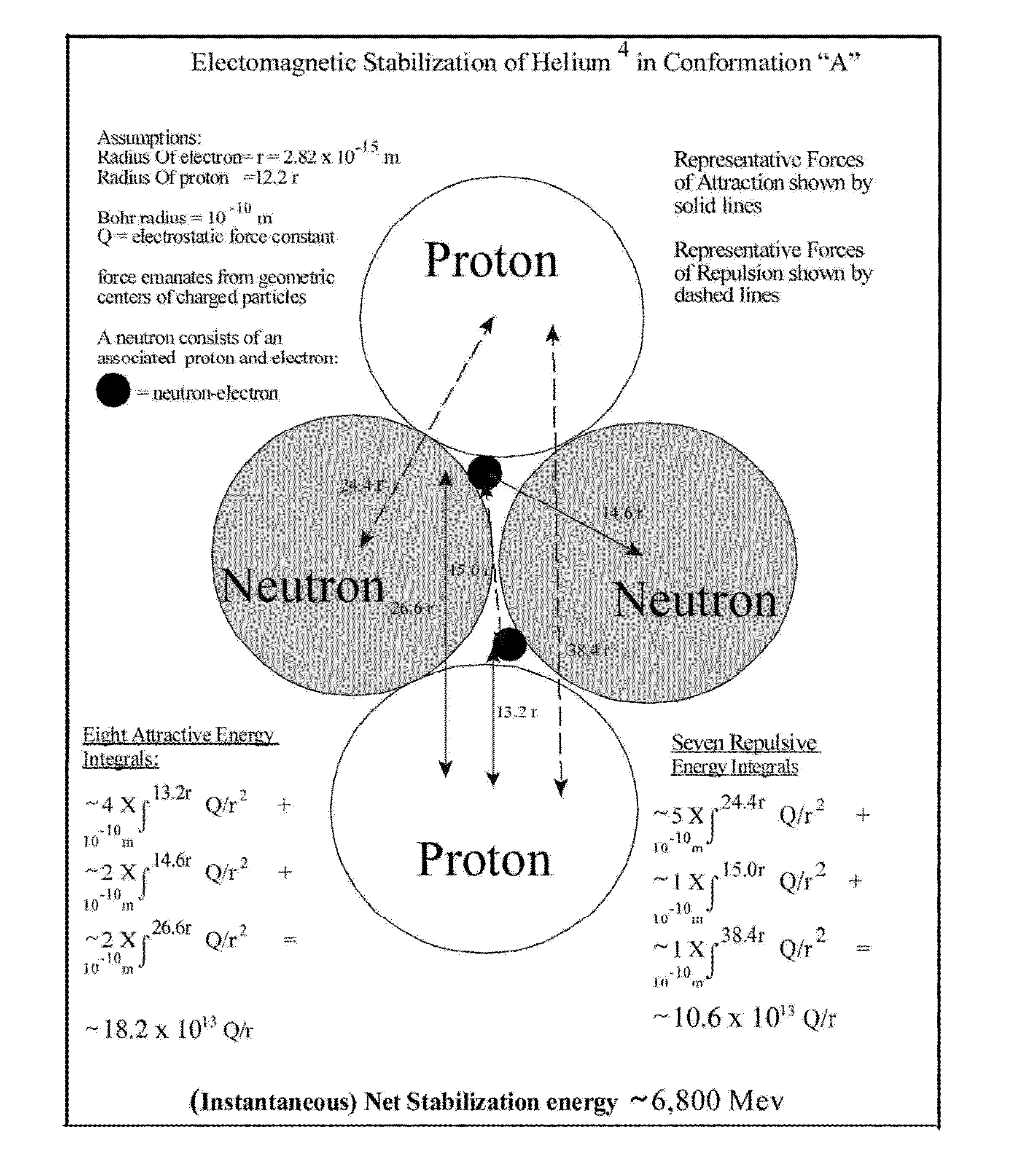
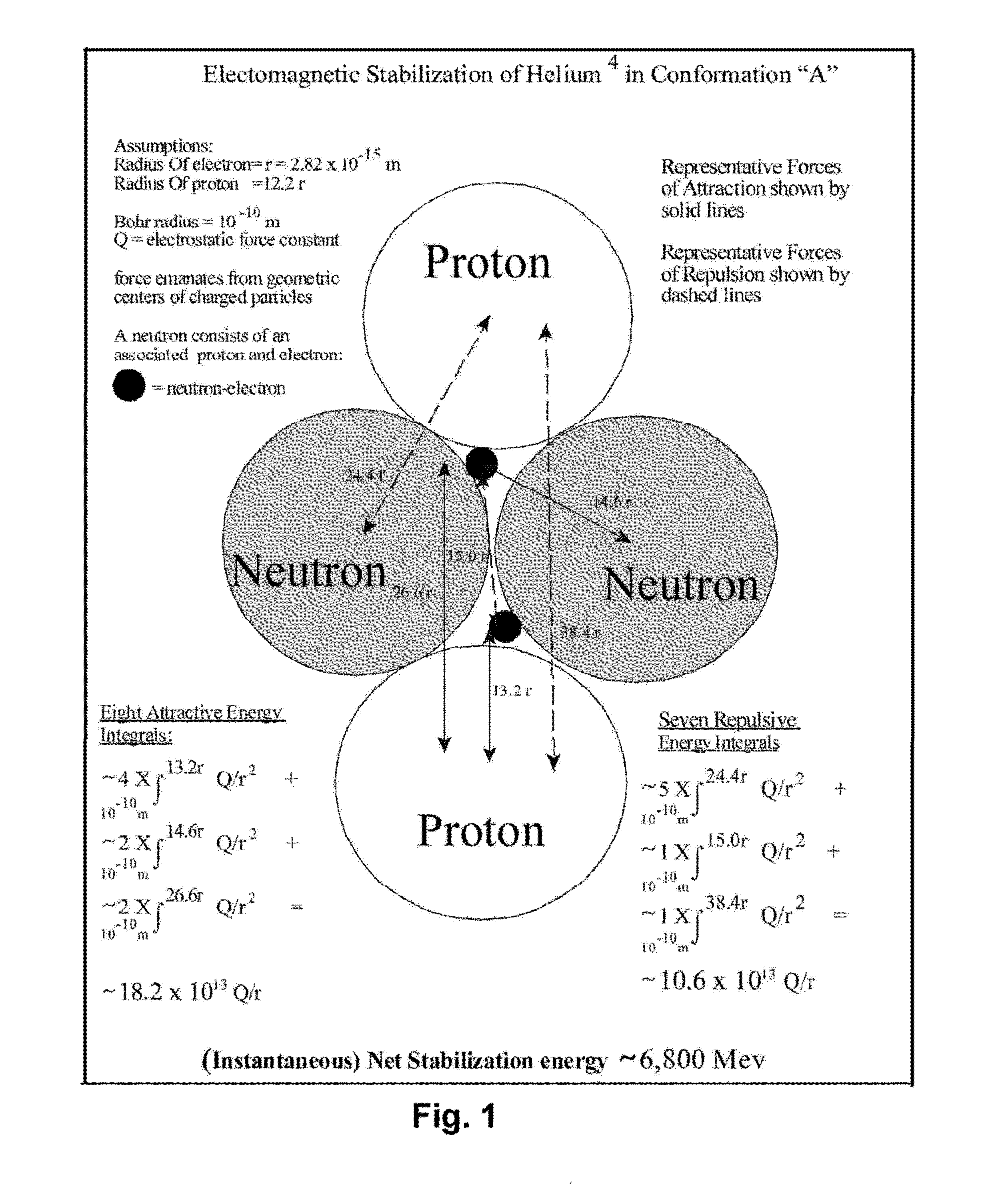
[0047]Referring now to the drawings of FIGS. 1-10 which depict modes of the device 10 and method herein. The disclosed method and device 10, provides a system for impelling lower energy barrier (catalytic) electromagnetic element reactions between deuterium ions, thereby producing useful helium-4. The method herein, using a combination of coordinated forces including surface force (optionally), a single vector magnetic force, motion-related mechanical force, gas pressure flow force (or other directional physical flow) and electromotive force to achieve the reactions between deuterium ions. A representative depiction of the forces and the calculations thereof can be viewed in FIG. 1 herein which provides such calculations validating this method and apparatus along with a simple schematic allowing an easy understanding of the noted forces.

[0048]In all modes of the device 10 to enable and coordinate the method herein, two populations of deuterium are employe...


PUM


Abstract

A method and device for production of helium and recoverable energy is provided. The system directs a first directionalized flow of a of a first streaming population of deuterium ions to an intersection with a second directionalized flow of a second streaming population of deuterium ions opposite the first stream. At or proximate to an intersection of the two streams helium and waste energy are produced and captured.

Description

BACKGROUND OF THE INVENTION[0001]1. Field of the Invention[0002]This application claims priority to U.S. Provisional Patent application Ser. No. 61 / 842,848 filed on Jul. 3, 2013 which is included herein in its entirety by this reference thereto.[0003]The present invention relates to a manner for producing helium. More particularly, the invention relates to method and electromagnetic element reactor device configured to produce helium and allowing for a concurrent harvesting of waste energy as a byproduct of that production.[0004]2. Prior Art[0005]Prior art conceptions regarding the reaction of hydrogen and its isotopes to form helium have invoked terminology such as “gluons” and “muons” as proposed explanations for this phenomenon, although these theorems are not mechanistically enabling. It has been attempted by practitioners of the prior art to form helium with associated energy during the reaction, from gaseous hydrogen and its isotopes. In these prior efforts, the employment of ...

Claims


Application Information

Patent Timeline
Patent Type & Authority Applications(United States)
IPC IPC(8): G21B1/11
CPCG21B1/11G21B3/006Y02E30/10
Inventor BURDICK, CHARLES
Owner BURDICK CHARLES
Why Eureka
Try Eureka