Electro-optic display with controlled electrochemical reactions

a technology of electrochemical reactions and electrochemical displays, applied in optics, instruments, optical elements, etc., can solve the problems of inadequate service life of these displays, unable to meet the needs of customers, and gas-based electrophoretic media are susceptible to the same types of problems, so as to reduce the remnant voltage

Active Publication Date: 2015-01-15
E INK CORPORATION
View PDF5 Cites 30 Cited by
  • Summary
  • Abstract
  • Description
  • Claims
  • Application Information

AI Technical Summary

Benefits of technology

[0048]In prior displays, there is no provision for controlled electrochemical reactions to occur at the electrode interfaces (i.e., to allow controlled charge injection from the electrodes). In contrast, in displays of the present invention, redox compounds are incorporated in layers adjacent the electrodes (or are incorporated into the displays in ways which permit them to diffuse adjacent the electrodes), thus permitting controlled electrochemical reactions to occur. Such electrochemical reactions may be reversible, partially reversible, or irreversible, and serve two purposes, namely to decrease the remnant voltage observed with DC-imbalanced driving, and to protect the electrode materials from irreversible degradation. With the addition of these redox compounds, DC-imbalanced driving can be effected without incurring an objectionable level of reversible or irreversible damage to the display.

Problems solved by technology

Nevertheless, problems with the long-term image quality of these displays have prevented their widespread usage.
For example, particles that make up electrophoretic displays tend to settle, resulting in inadequate service-life for these displays.
Such gas-based electrophoretic media appear to be susceptible to the same types of problems due to particle settling as liquid-based electrophoretic media, when the media are used in an orientation which permits such settling, for example in a sign where the medium is disposed in a vertical plane.
Indeed, particle settling appears to be a more serious problem in gas-based electrophoretic media than in liquid-based ones, since the lower viscosity of gaseous suspending fluids as compared with liquid ones allows more rapid settling of the electrophoretic particles.
However, the methods used for assembling LCD's cannot be used with solid electro-optic displays.
This LCD assembly process cannot readily be transferred to solid electro-optic displays.
It is in general preferred that all individual waveforms within a drive scheme be DC balanced, but in practice this has been difficult to achieve, so typical drive schemes have usually been a mixture of DC balanced and DC imbalanced waveforms, even though the drive scheme as a whole has been DC balanced.
If its remnant voltage is positive, it is taken to be DC unbalanced in the positive direction.
If its remnant voltage is negative, it is taken to be DC unbalanced in the negative direction.
Non-zero remnant voltages have been found to correlate with difficulties in accurate gray level placement.
In cases where a prior art electrophoretic display is driven with extreme degrees of DC-imbalance, however, it is possible that the electrodes may be irreversibly degraded, presumably by electrochemical reactions that consume the electrode materials.
Although DC-balanced driving waveforms effectively protect against development of remnant voltages and electrode degradation there are problems associated with their use.
In addition, distracting optical transitions may be visible to the user of the display during DC-balanced updates.

Method used


Image

  • Electro-optic display with controlled electrochemical reactions
  • Electro-optic display with controlled electrochemical reactions
  • Electro-optic display with controlled electrochemical reactions

Examples


example 1

[0082]This Example illustrates the reduction in remnant voltage and electrode damage following DC imbalanced driving of a display of the present invention, as compared with a control display lacking a redox compound.

[0083]Experimental displays were prepared as follows:

[0084]Part A: Preparation of a Solution of Redox Compounds

[0085]An oxidized form of a redox compound (tetramethylbenzoquinone, 370 mg, 2.3 mmole) and a reduced form of a redox compound (phenidone, 190 mg, 1.2 mmole) were added to isopropanol (10 g) and the mixture was sonicated at 35° C. for 15 minutes.

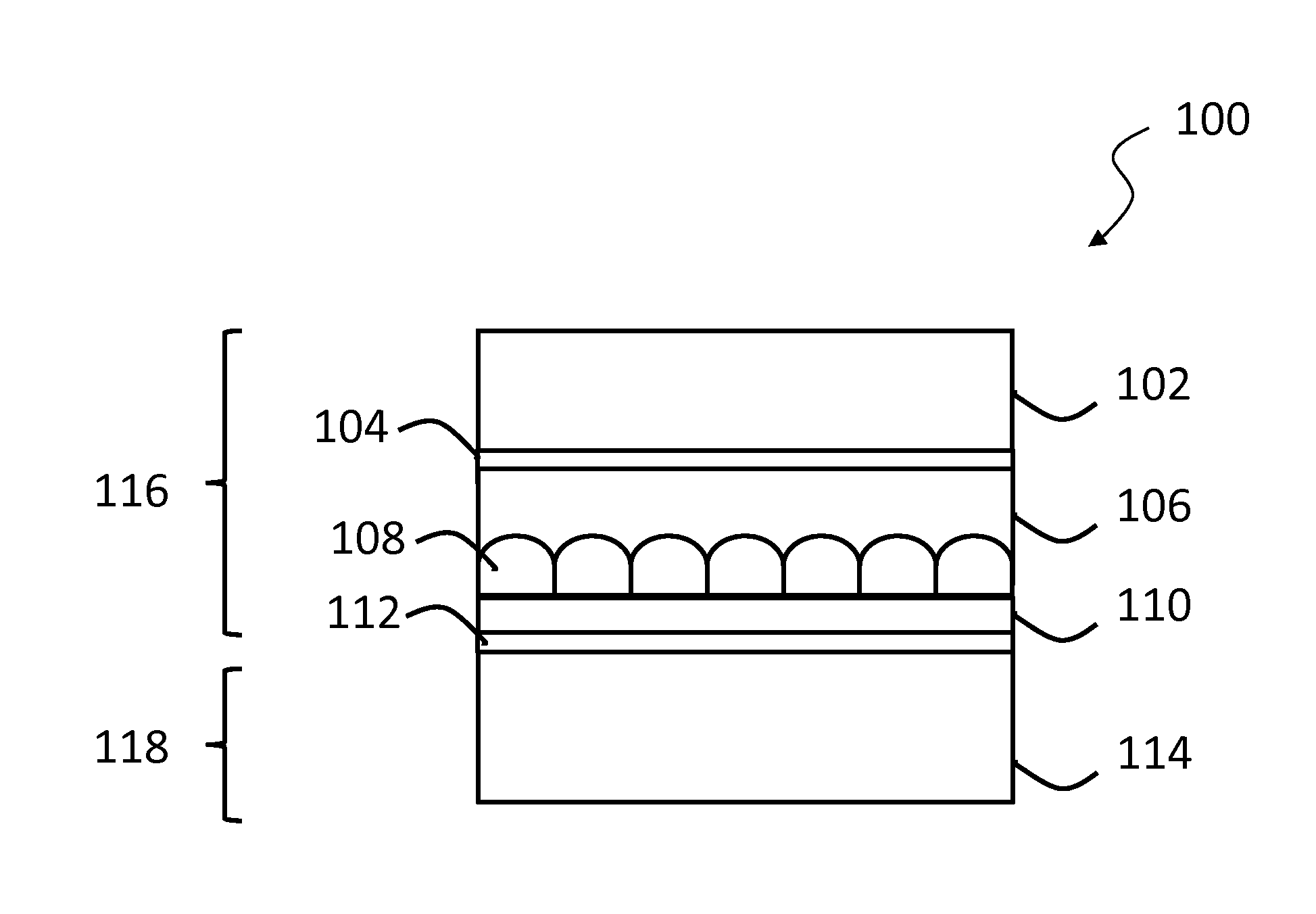
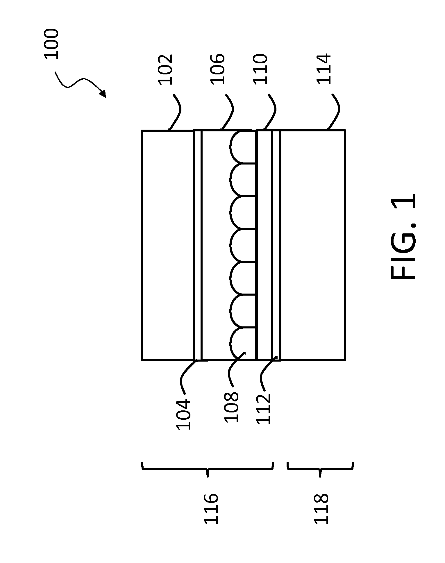
[0086]Part B: Preparation of a Lamination Layer (Corresponding to Layer 106 in FIG. 1)

[0087]The redox compound solution prepared in Part A above (7.8 g) was added to 92.2 g of a 35 percent by weight aqueous dispersion of a polyurethane latex of the type described in U.S. Pat. No. 7,342,068 and the mixture was homogenized on a roll mill. The resultant mixture was coated on to a poly(ethylene terephthalate) (PET) film base...

example 2

[0095]This Example illustrates the improved stability of white and dark states following a DC-imbalanced drive achieved by a display of the present invention as compared with a control lacking the redox compounds.

[0096]Experimental displays produced in Example 1 above with PET / carbon backplanes were compared with similar control displays lacking the redox compounds. The displays were driven to the white state in a highly imbalanced manner by applying the following waveform: three iterations of ten 250 ms pulses of +15 V (top plane) each, separated by 1 second at 0 V, with 5 seconds at 0 V after the tenth pulse, followed by 25 seconds at 0 V. The difference between the white state measured at the end of the final 15 V pulse and that measured at the end of the whole waveform was recorded. Similarly, the displays were driven to the dark state with the same waveform except with −15 V pulses and the difference between the dark state measured at the end of the final −15 V pulse and that m...


PUM

PropertyMeasurementUnit
reduction potentialaaaaaaaaaa
molecular weightaaaaaaaaaa
reduction potentialaaaaaaaaaa

Abstract

An electro-optic display has a viewing surface through which a user views the display, a bistable, non-electrochromic electro-optic medium, and at least one electrode arranged to apply an electric field to the electro-optic medium, the display. The display comprises at least 10 micromoles per square meter of the viewing surface of at least one redox compound having an oxidation potential more negative that about 150 mV with respect to a standard hydrogen electrode, as measured at pH 8.

Description

REFERENCE TO RELATED APPLICATIONS[0001]This application claims benefit of copending Application Ser. No. 61 / 750,980, filed Jan. 10, 2013.[0002]This application also is related to U.S. Pat. Nos. 6,724,519 and 7,564,614.[0003]The entire contents of these patents and copending application, and of all other U.S. patents and published and copending applications mentioned below, are herein incorporated by reference.BACKGROUND OF INVENTION[0004]This invention relates to an electro-optic display with controlled electrochemical reactions. More specifically, this invention relates to a bistable, non-electrochromic electro-optic display incorporating controlled oxidation / reduction reactions at at least one interface between electronically-conductive and ionically-conductive display components.[0005]The terms “bistable” and “bistability” are used herein in their conventional meaning in the art to refer to displays comprising display elements having first and second display states differing in a...

Claims


Application Information

Patent Timeline
Patent Type & Authority Applications(United States)
IPC IPC(8): G02F1/167G02F1/1676
CPCG02F2001/1678G02F1/167G02F1/1676G02B26/005G02F1/155G02F1/1681G02B26/00G02B5/201G02B26/026
Inventor TELFER, STEPHEN J.WIDGER, PETER CARSTEN BAILEYLATTES, ANA L.LAUBER, DAN JOHN
Owner E INK CORPORATION
Why Eureka
Try Eureka