Ultra Light Bar Armor

a technology of armor and light bars, applied in the field of vehicles and armor, can solve the problems of inability to use steel for rpg protection on most vehicles, difficult to counter, and still relatively heavy, and achieve the effects of preventing bar spreading, low aereal density, and sufficient strength

Inactive Publication Date: 2015-01-22
HAFER THOMAS FREDERICK
View PDF2 Cites 4 Cited by
  • Summary
  • Abstract
  • Description
  • Claims
  • Application Information

AI Technical Summary

Benefits of technology

[0005]It is therefore an object of the present invention to provide an improved bar armor solution for protection against RPGs by inhibiting lateral spreading of the bars through the use of low density frangible cross-attachment members between the bars that provide sufficient strength to prevent bar spreading and are also of low enough aereal density and of sufficient frangibility to avoid detonation of the RPG if the cross-attachment members are struck by the nosepiece of the RPG, thus allowing thinner bars to be used than would otherwise be possible.
[0006]It is a further object of the present invention to provide a means of reducing the weight of bar armor.
[0007]It is a further object of the present invention to provide a means of increasing the effectiveness of bar armor.
[0008]It is a further object of the present invention to provide a means of improving the visibility through bar armor.
[0009]It is a further object of the present invention to reduce the cost of bar armor systems.

Problems solved by technology

They are cheap, effective, and difficult to counter.
RPGs can penetrate as much as a foot of steel armor, so it is not practical to use steel for RPG protection on most vehicles because of the weight.
Bar and slat armor is much lighter than steel would be, but is still relatively heavy when applied to large areas of an armored vehicle, adding hundreds or even thousands of pounds.
With low cost materials, these dimensions cannot easily be reduced because the resultant low lateral strength allows the bars or slats to be pushed apart by the RPG ogive without inflicting sufficient damage.

Method used


Image

  • Ultra Light Bar Armor
  • Ultra Light Bar Armor
  • Ultra Light Bar Armor

Examples


Embodiment Construction

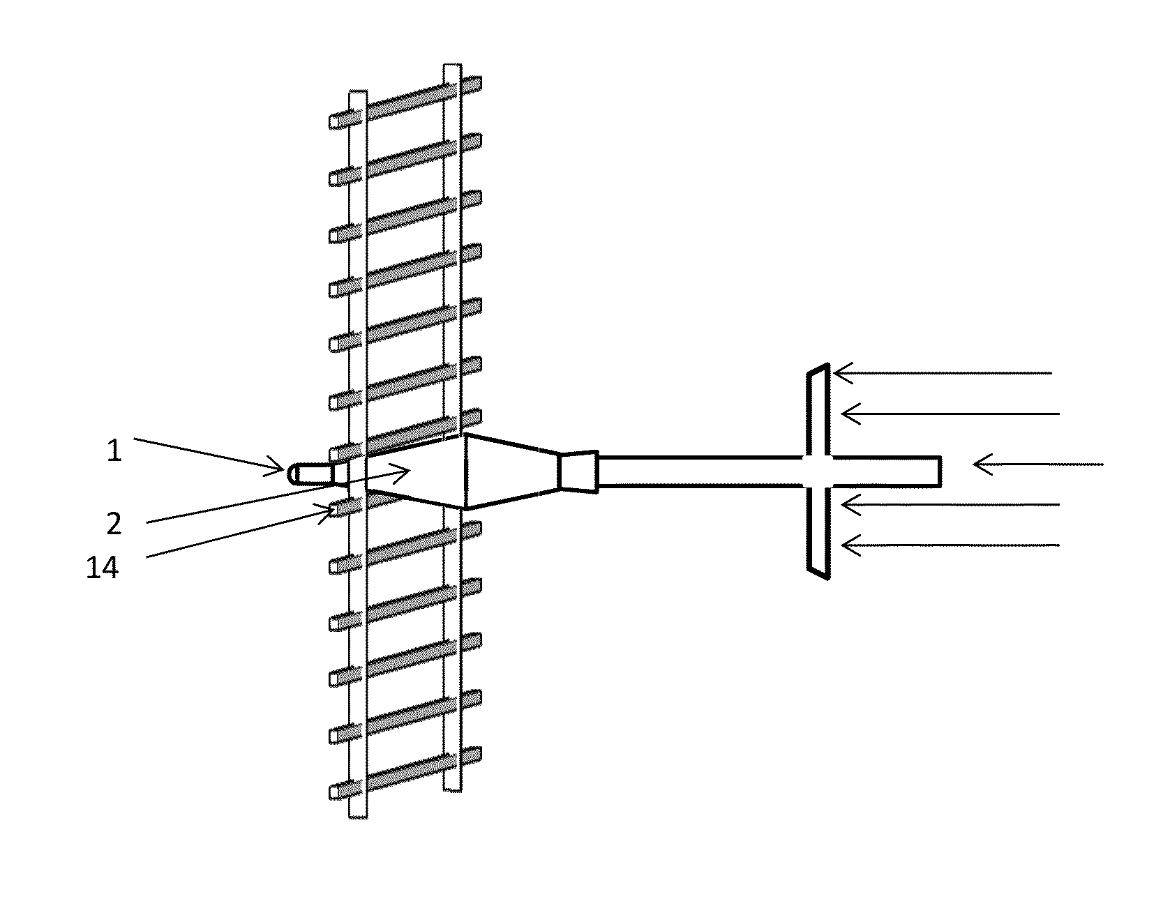
[0024]The present invention improves the performance of bar armor against RPGs by inhibiting the spreading of the bars, thus allowing smaller cross section bars to be used. This can result in lighter weight, improved performance, improved visibility through the bars, and lower cost.

[0025]To understand how this works, it is first necessary to understand the operation of an RPG and of bar armor.

RPG and Bar Armor Operation

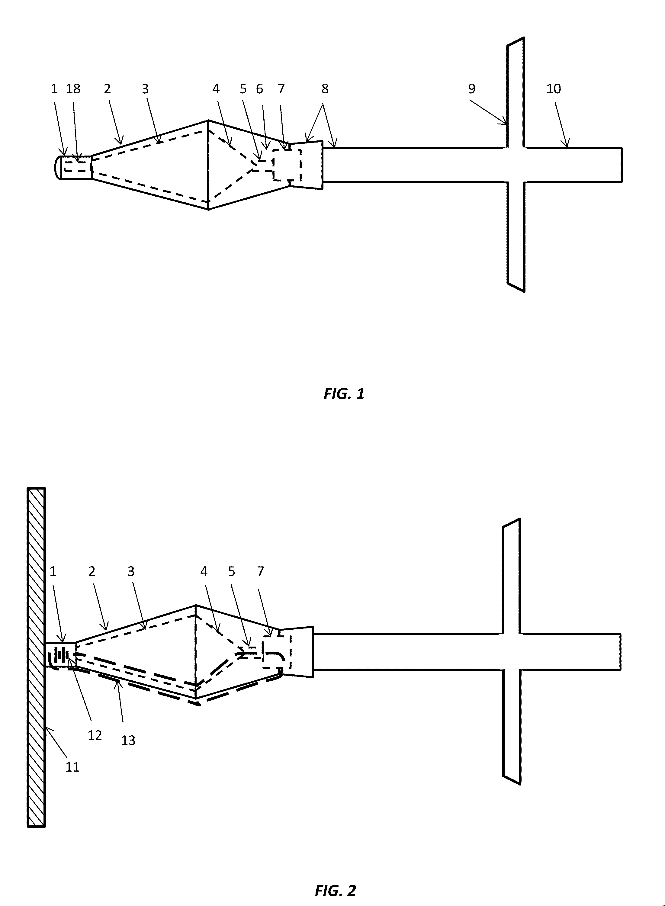
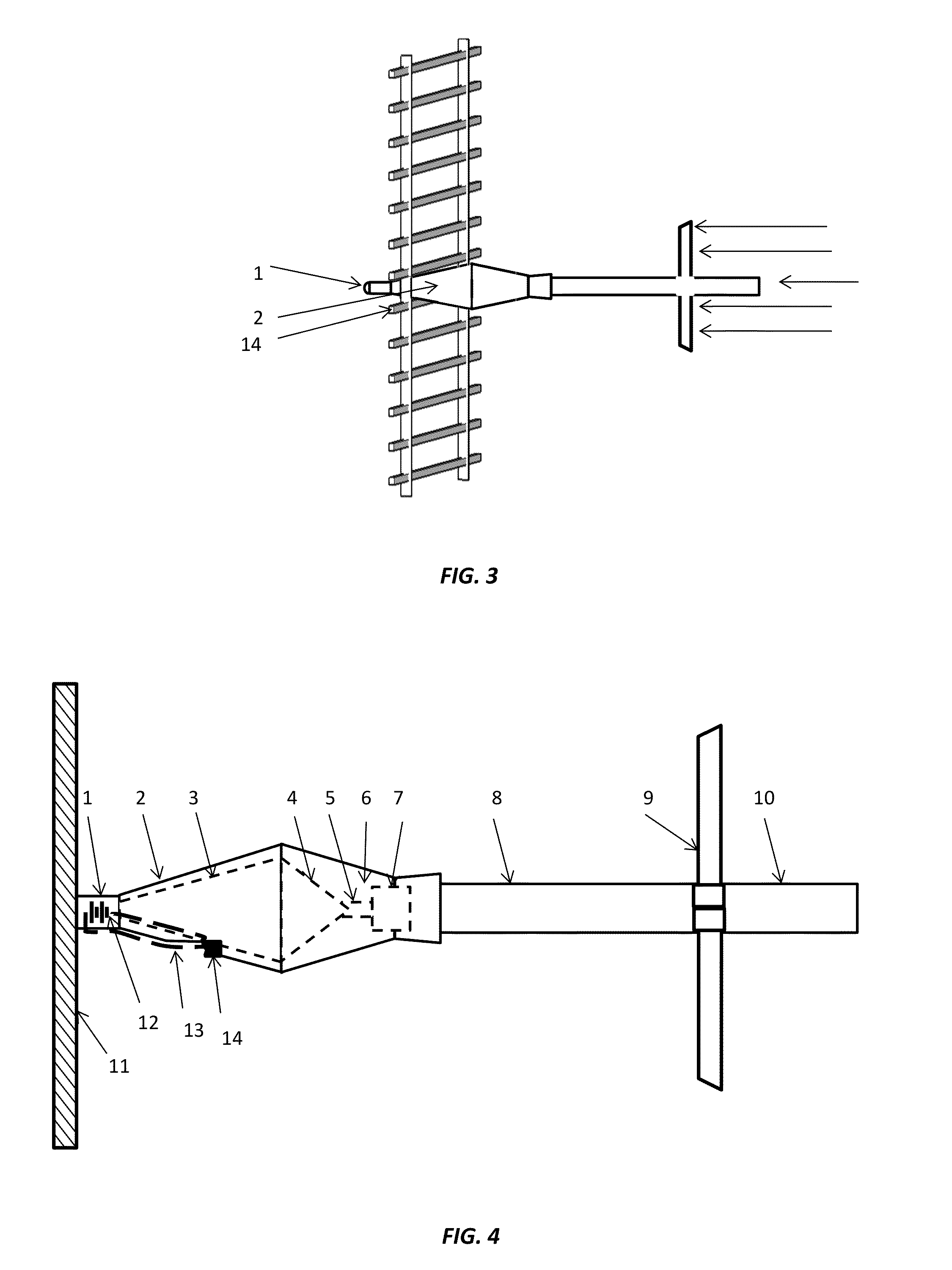
[0026]Referring to FIG. 1, the RPG is about 37 inches long and the warhead has a maximum diameter of about 3½ inches. The nosepiece 1 is approximately 1 inch in diameter and contains a piezoelectric crystal 18 that produces a voltage when it strikes a target. Behind that are the hollow aluminum outer ogive 2 and the hollow aluminum inner ogive 3. These provide standoff to allow the warhead to function optimally. The warhead consists of the hollow copper shaped charge liner 4, the conductive stem 5, the explosive 6, and the initiating fuse 7. Behind these are the fligh...


PUM


Abstract

Bar armor currently provides a means of providing partial protection of vehicles and structures against certain types of Rocket Propelled Grenades (RPGs). However, the individual bars must provide enough strength to cut through or deform the outer ogive of an RPG and cause electrical contact with the inner ogive. This in turn imposes constraints on the overall effectiveness of the system and how light it can be made. These constraints can be eased by providing cross-attachments for the bars, provided that the cross-attachments themselves are of low enough density and sufficient frangibility to avoid detonating the RPG when they are struck by the RPG nosepiece, which contains a piezoelectric element that causes the fuse of the RPG to function. Through this means, bar armor can be made lighter, more effective, and easier to see through.

Description

RELATED APPLICATIONS[0001]This patent application claims priority over Provisional Patent Application 61 / 573449 filed on 6 Sep. 2011, incorporated herein by reference.FIELD OF THE INVENTION[0002]This invention generally relates to protection of vehicles and structures from Rocket Propelled Grenades. More particularly, it relates to reducing the weight and improving the effectiveness of bar armor by inhibiting bar separation by means of low density frangible connections between the bars.BACKGROUND OF THE INVENTION[0003]Rocket Propelled Grenades (RPGs) have been employed since World War II against armored vehicles and fortifications. They are cheap, effective, and difficult to counter. Currently, millions of these weapons are used by insurgent and guerilla forces, as well as regular forces in many countries. RPGs can penetrate as much as a foot of steel armor, so it is not practical to use steel for RPG protection on most vehicles because of the weight. To provide at least partial pro...

Claims


Application Information

Patent Timeline
Patent Type & Authority Applications(United States)
IPC IPC(8): F41H5/02F41H7/02F41H5/24
CPCF41H5/026F41H5/24F41H7/02
Inventor HAFER, THOMAS, FREDERICK
Owner HAFER THOMAS FREDERICK
Why Eureka
Try Eureka