Eye imaging apparatus and systems

a technology of eye imaging and apparatus, applied in the field of eye imaging apparatus and system, can solve the problems of difficult for clinicians to move the system within hospitals and/or to remote areas, the cart carrying the slit-lamp imaging system may be relatively heavy, and the system may lack mobility, etc., to achieve significant size reduction, high computing power, and high imaging performance

Inactive Publication Date: 2015-01-22
VISUNEX MEDICAL SYST
View PDF4 Cites 41 Cited by
  • Summary
  • Abstract
  • Description
  • Claims
  • Application Information

AI Technical Summary

Benefits of technology

[0007]Various embodiments also include an imaging apparatus that comprises a housing and an exterior imaging module, e.g., an anterior eye imaging module. The exterior imaging module comprises a lighting unit comprising a light source configured to illuminate an eye, and an image sensor disposed to receive an image of the eye. The exterior imaging module is disposed on an exterior portion of the housing. The imaging apparatus may also include a hand-held computing device and an adaptation module. The adaptation module comprises a microcontroller and a signal processing unit, thus allowing the hand-held computing device to control the light source and the image sensor.
[0021]Various embodiments include a hand-held eye imaging apparatus, which is compact and may be carried away to the remote rural areas. The hand-held eye imaging apparatus utilizes the advanced features of wireless data transmission and high computing power of a hand-held computing device. The hand-held eye imaging apparatus is capable to image both the posterior segment and the anterior segment of the eye. In addition, the hand-held eye imaging apparatus may also be connected with an ultrasound probe. The versatile hand-held eye imaging apparatus may use miniature cameras and solid state lighting technology to achieve high imaging performance and significant size reduction.

Problems solved by technology

However, slit imaging systems may lack mobility, such that it is difficult for the clinician to move the system within hospitals and / or to remote areas.
For example, the cart carrying the slit-lamp imaging system may be relatively heavy and difficult to move.
The computer or console associated with the system, and other system accessories, may reduce the portability of the system within hospitals, and may also reduce the ability to move the system to and / or from remote rural areas.
It may be inconvenient and time consuming to switch the patients from one eye imaging apparatus to another.
It may be difficult to transfer medical data among different geographical locations and different hospitals.
The problems associated with transfer of medical data may be more severe for developing countries where the access to the hospitals or eye care clinics is more limited.

Method used


Image

  • Eye imaging apparatus and systems
  • Eye imaging apparatus and systems
  • Eye imaging apparatus and systems

Examples


Embodiment Construction

[0370]The present invention now will be described in detail with reference to the accompanying figures. This invention may be embodied in many different forms and should not be construed as limited to the exemplary embodiments discussed herein.

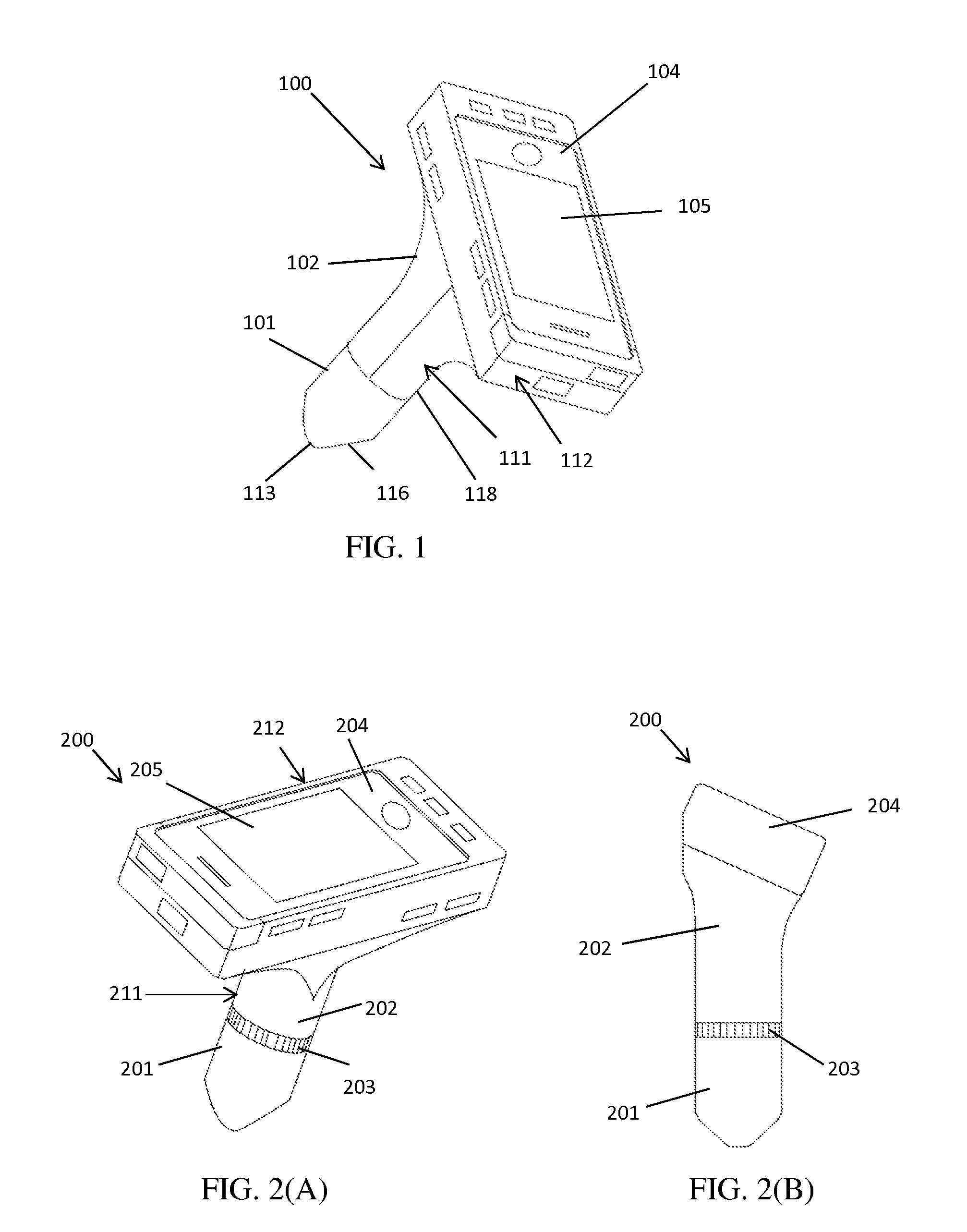
[0371]FIG. 1 schematically illustrates a hand-held eye imaging apparatus 100, according to various embodiments. For example, the eye imaging apparatus 100 can comprise a housing comprising a cylindrical portion 111 and a cuboid portion 112. The cuboid portion 112 can be mounted on top of the cylindrical portion 111 in some embodiments. The cylindrical portion 111 can have a tapered front portion 116, which may be closer to an eye of a patient during an examination procedure. The cylindrical portion 111 can have a length between about 50 mm and about 200 mm, and a diameter between about 20 mm and about 80 mm in some embodiments. The cylindrical portion 111 can have a front portion 116 and a back portion 118. The front portion 116 of the cylindr...


PUM

PropertyMeasurementUnit
distanceaaaaaaaaaa
distanceaaaaaaaaaa
convergent angleaaaaaaaaaa

Abstract

Various embodiments of an eye imaging apparatus are disclosed. In some embodiments, the eye imaging apparatus may comprise a light source, an image sensor, a hand-held computing device, and an adaptation module. The adaptation module comprises a microcontroller and a signal processing unit configured to adapt the hand-held computing device to control the light source and the image sensor. In some embodiments, the imaging apparatus may comprise an exterior imaging module to image an anterior segment of the eye and / or a front imaging module to image a posterior segment of the eye. The eye imaging apparatus may be used in an eye imaging medical system. The images of the eye may be captured by the eye imaging apparatus, transferred to an image computing module, stored in an image storage module, and displayed in an image review module.

Description

CROSS-REFERENCE TO RELATED APPLICATIONS[0001]This application is a continuation-in-part of U.S. patent application Ser. No. 13 / 757,798, filed on Feb. 3, 2013, which claims priority to U.S. Provisional Patent Application No. 61 / 593,865, filed on Feb. 2, 2012, each of which is incorporated by reference herein in its entirety and for all purposes.BACKGROUND OF THE INVENTION[0002]Embodiments of the invention relate generally to an eye imaging apparatus and system, for example, a hand-held eye imaging apparatus and related systems.[0003]Eye imaging apparatuses have become increasingly important in eye examinations. Early diagnosis of eye diseases is often important in effective treatment and prevention of vision loss. In general, a comprehensive eye examination may include an examination of the anterior segment (such as the cornea), an examination of the posterior segment (such as the retina), and a vision function examination.[0004]Conventionally, slit-lamp imaging systems may be used f...

Claims


Application Information

Patent Timeline
Patent Type & Authority Applications(United States)
IPC IPC(8): A61B19/00A61B19/02A61B3/14
CPCA61B19/026A61B2019/0274A61B3/14A61B19/34A61B3/0016A61B3/12A61B2019/025A61B2019/0265A61B2050/311A61B90/70A61B50/13A61B50/30A61B50/31H04N1/00246A61B3/0025A61B3/0033A61B2560/0431G02B7/023A61B3/0058A61B3/117A61B3/125A61B3/145A61B8/10A61B8/4416A61B8/4427A61B8/463A61B8/467A61B8/52G02B7/04
Inventor SU, WEIXU, LI
Owner VISUNEX MEDICAL SYST
Why Eureka
Try Eureka