Method and System for Through-the-Wall Imaging using Sparse Inversion for Blind Multi-Path Elimination

a technology of sparse inversion and through-the-wall imaging, applied in multi-channel direction-finding systems using radio waves, instruments, measurement devices, etc., can solve problems such as inability to achieve practical application, ghost artifacts in images that appear as noise, etc., and achieve the effect of suppressing ghosting artifacts

Active Publication Date: 2015-01-22
MITSUBISHI ELECTRIC RES LAB INC
View PDF1 Cites 15 Cited by
  • Summary
  • Abstract
  • Description
  • Claims
  • Application Information

AI Technical Summary

Benefits of technology

[0014]A distortion of the pulse after the pulse passes through the wall but before the pulse is reflected by the target can also be determined. The distortion is used in an iterative process to refine the detection of the targets and to suppress ghosting artifacts.

Problems solved by technology

Depending on a dielectric permittivity and permeability of the wall, the received signal is often corrupted with indirect, secondary reflections from the wall, which result in ghost artifacts in an image that appear as noise.
However, all of the above techniques assume perfect knowledge of a reflective geometry of the scene, which is not necessarily feasible in practice.

Method used


Image

  • Method and System for Through-the-Wall Imaging using Sparse Inversion for Blind Multi-Path Elimination
  • Method and System for Through-the-Wall Imaging using Sparse Inversion for Blind Multi-Path Elimination
  • Method and System for Through-the-Wall Imaging using Sparse Inversion for Blind Multi-Path Elimination

Examples


Embodiment Construction

System Setup

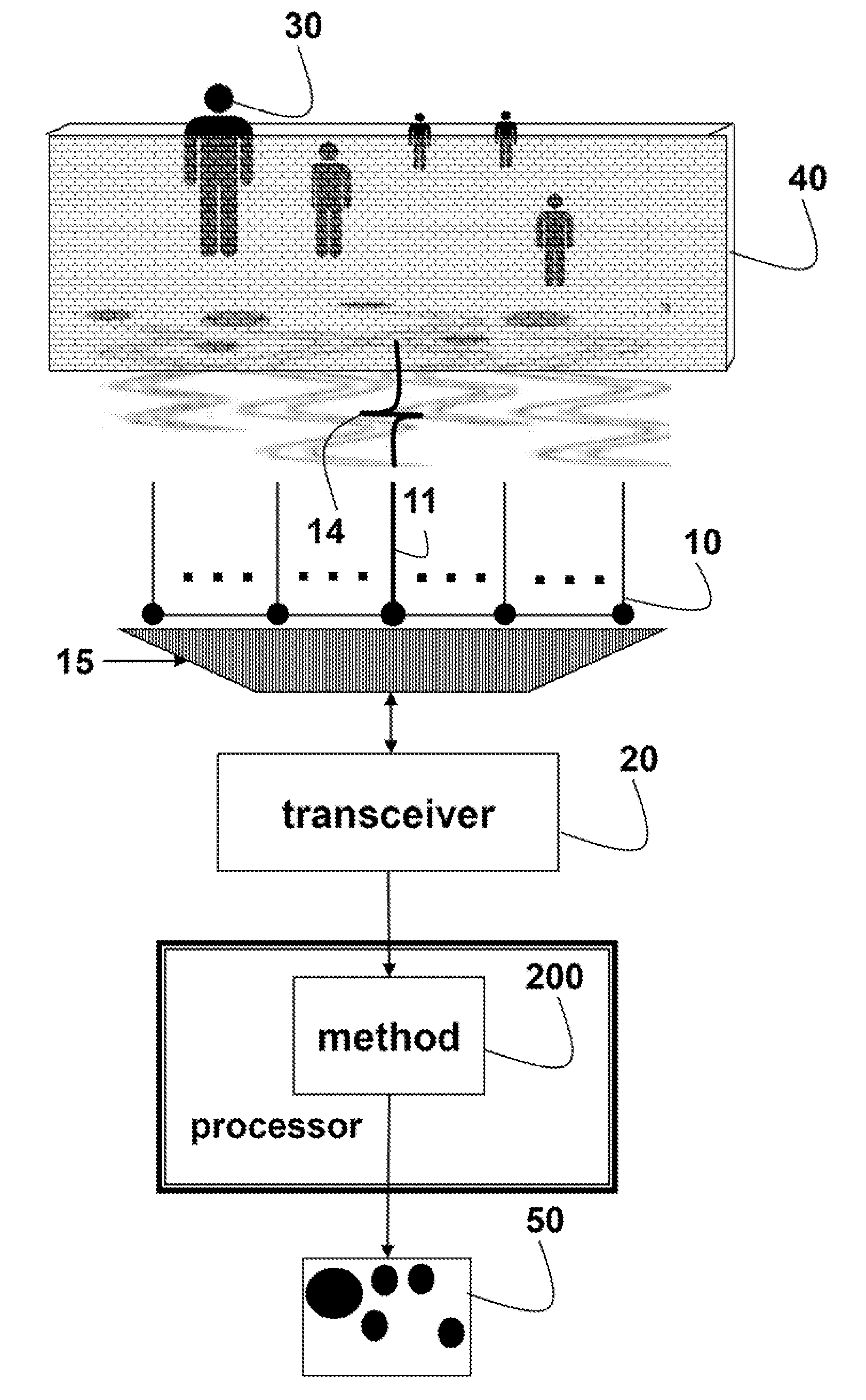
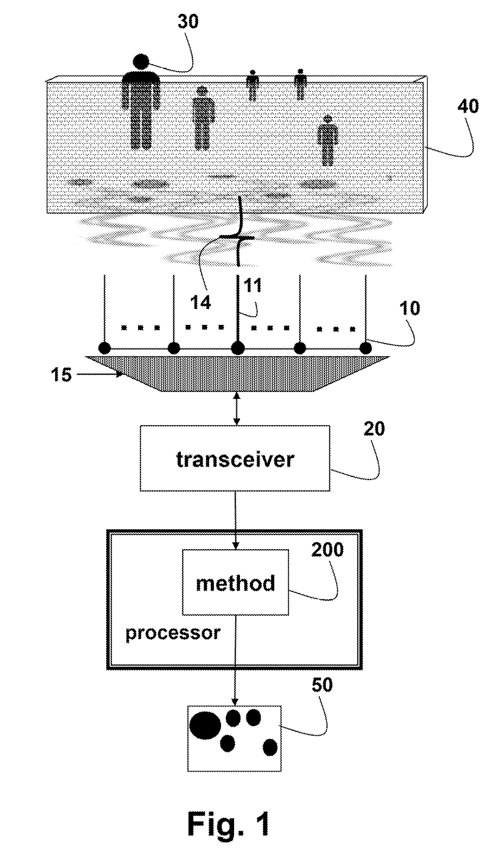
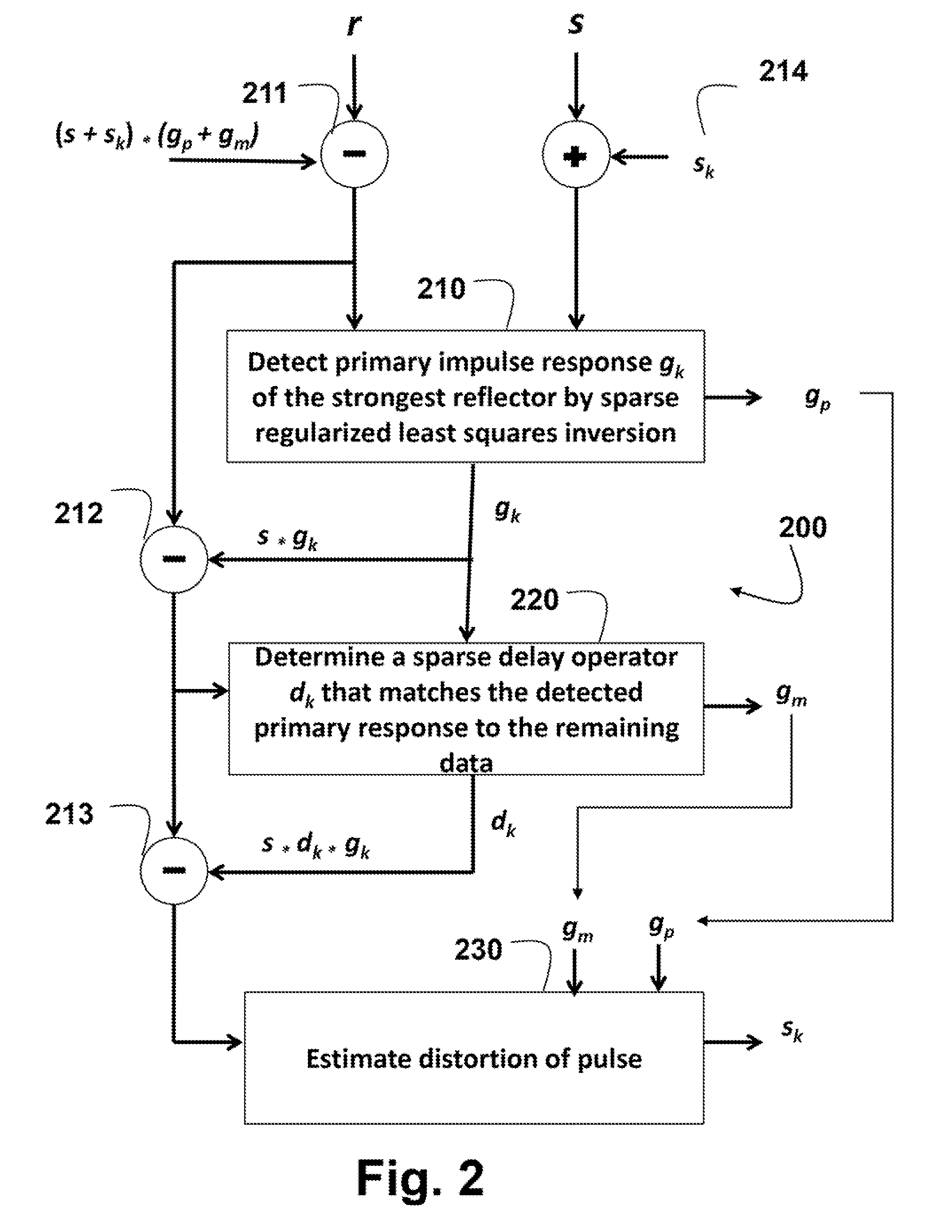
[0018]As shown in FIGS. 1 and 2, the embodiments of my invention provide a method 200 for multi-path removal in physical aperture and synthetic aperture radar (SAR) through-the-wall imaging (TWI) of targets 30 that does not require any prior knowledge of scene geometry. As an advantage, the method reduces ghosting artifacts by iteratively refining detected impulse responses.

[0019]A transceiver 20 transmits one or more pulses 14 by, e.g., selecting 15 a central antenna element 11 of an antenna array 10 with, for example, 21 elements. The receiving elements are half-wavelength apart:, which is 3 cm for a pulse with a central frequency ƒc=5 GHz. Typically, through-the-wall radar and imaging systems operate in the ultra-wide band (UWB) from about 1.6 to about 10.5 GHz. 5. if the antenna array has a non-uniform separation distance between the elements, then, the time-domain data can be interpolated. In this case, the resolution of the output matches a smallest separation betw...


PUM


Abstract

Targets are detected in a scene behind a wall by first transmitting a pulse through the wall. Then, a primary impulse response is detected by a sparse regularized least squares inversion applied to received signals corresponding to the reflected pulse. A delay operator that matches the primary impulse response to similar impulse responses in the received signals is also determined. A distortion of the pulse after the pulse passes through the wall but before the pulse is reflected by the target can also be determined. The distortion is used in an iterative process to refine the detection of the target and to suppress ghosting artifacts.

Description

FIELD OF THE INVENTION[0001]This invention relates generally to through-the-wall imaging, and more particularly to using sparse inversion for multi-path elimination.BACKGROUND OF THE INVENTION[0002]Through-the-wall-imaging (TWI) can be used to detect objects inside enclosed structures. In TWI, a transmitter emits an electromagnetic (EM) radar pulse, which propagates through a wall. The pulse is reflected by a target on the other side of the wall, and then propagates back to a receiver as an impulse response convolved with the emitted pulse. Typically, the transmitter and receiver use an antenna array.[0003]Depending on a dielectric permittivity and permeability of the wall, the received signal is often corrupted with indirect, secondary reflections from the wall, which result in ghost artifacts in an image that appear as noise. Wall clutter mitigation techniques attempt to eliminate the artifacts that arise from the multi-path reflections in TWI.[0004]Some methods derive multi-path ...

Claims


Application Information

Patent Timeline
Patent Type & Authority Applications(United States)
IPC IPC(8): G01S13/88
CPCG01S13/888G01S3/74G01S7/292G01S13/89
Inventor MANSOUR, HASSAN
Owner MITSUBISHI ELECTRIC RES LAB INC
Why Eureka
Try Eureka