Lighting device and method for manufacturing the same

a technology of light source and light source, which is applied in the direction of semiconductor devices for light sources, light and heating apparatus, transportation and packaging, etc., can solve the problems of shortening the life and heat radiation, and achieve the effect of increasing mass productivity and reducing costs

Inactive Publication Date: 2015-01-22
SAMSUNG ELECTRONICS CO LTD
View PDF25 Cites 26 Cited by
  • Summary
  • Abstract
  • Description
  • Claims
  • Application Information

AI Technical Summary

Benefits of technology

[0010]An aspect of the present inventive concept relates to a lighting device capable of increasing mass productivity and

Problems solved by technology

Regarding products including the LED, heat radiation is a significant issue b

Method used


Image

  • Lighting device and method for manufacturing the same
  • Lighting device and method for manufacturing the same
  • Lighting device and method for manufacturing the same

Examples


Embodiment Construction

[0055]Examples of the present inventive concept will be described below in more detail with reference to the accompanying drawings. The examples of the present inventive concept may, however, be embodied in different forms and should not be construed as limited to the examples set forth herein. Like reference numerals may refer to like elements throughout the specification.

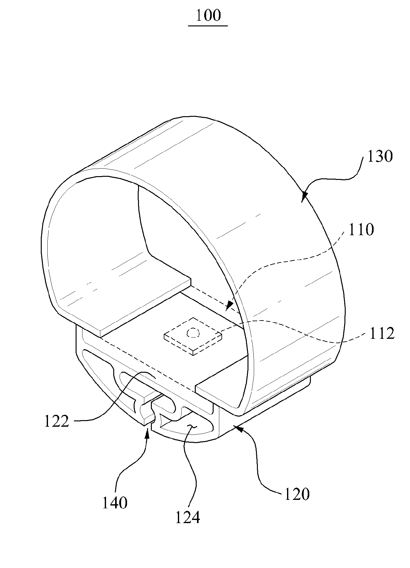
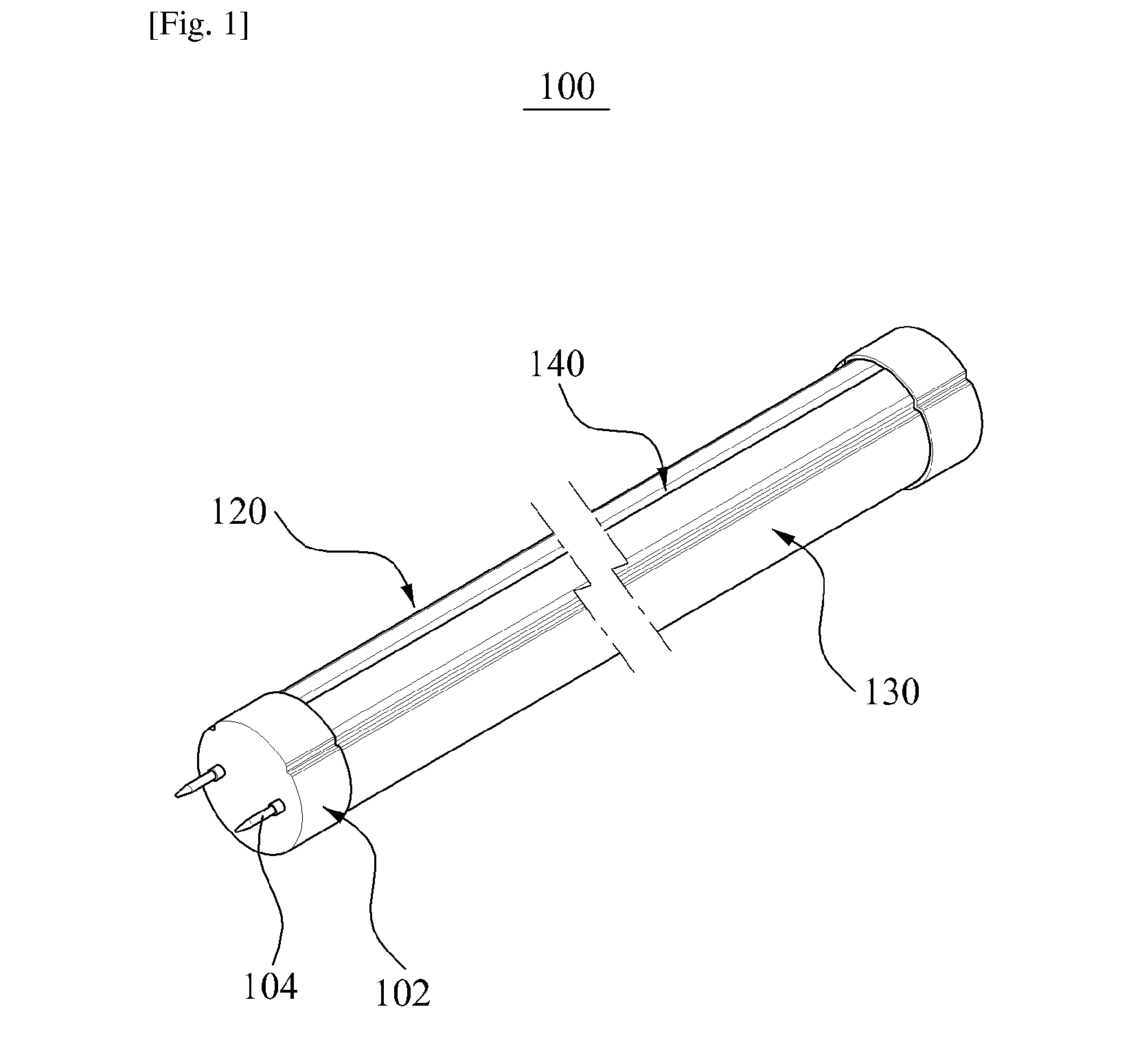
[0056]FIG. 1 is a perspective view of a lighting device 100 according to an embodiment of the present inventive concept. FIG. 2 is a perspective view illustrating main elements of the lighting device 100 shown in FIG. 1. FIG. 3 is a sectional view illustrating main elements of the lighting device 100 shown in FIG. 2.

[0057]Referring to FIGS. 1 to 3, the lighting device 100 may include a circuit substrate 110, a heat sink 120, a cover 130, and a shape control portion 140.

[0058]Hereinafter, the lighting device 100 will be described as a tube-type lighting device although the lighting device 100 may be applicable to v...


PUM

PropertyMeasurementUnit
Efficiencyaaaaaaaaaa
Shapeaaaaaaaaaa
Efficiencyaaaaaaaaaa

Abstract

A lighting device in which a heat sink and a cover are formed by co-extrusion and a manufacturing method for the same are provided. The heat sink and the cover may be co-extruded. A shape control portion may be formed at the heat sink to control a shape of a seating portion to seat a circuit substrate during extrusion of the heat sink. In addition, a light characteristic control portion may be provided between a light emitting diode (LED) and the cover to control characteristic of light generated from the LED.

Description

CROSS-REFERENCE TO RELATED APPLICATIONS[0001]This application is a U.S. National Stage Application, which claims the benefit under 35 U.S.C. §371 of PCT International Patent Application No. PCT / KR2013 / 002523, filed Mar. 27, 2013, which claims the foreign priority benefit under 35 U.S.C. §119 of Korean Patent Application No. 10-2012-0033625, filed Mar. 30, 2012, and of Korean Patent Application No. 10-2012-0033624, filed Mar. 30, 2012, the contents of which are incorporated herein by reference.BACKGROUND[0002]1. Field[0003]The present inventive concept relates to a lighting device including a light emitting diode (LED), and more particularly, to a lighting device for increasing mass productivity and reducing cost by manufacturing a heat sink and a cover by co-extrusion.[0004]2. Description of Related Art[0005]A light emitting diode (LED) refers to a semiconductor device that emits light as an electric current flows. For example, the LED refers to a p-n junction diode including galliu...

Claims


Application Information

Patent Timeline
IPC IPC(8): F21V29/00F21V9/00F21K99/00
CPCF21V29/2206F21K9/90F21Y2101/02F21V9/00F21K9/56F21Y2103/003F21V29/763F21K9/17F21K9/27F21K9/64F21Y2101/00F21Y2103/10F21Y2115/10F21K9/275F21K9/69F21V9/20F21V29/74Y10T29/4913
Inventor YU, BYEONG HYEONLEE, WOOK PYOTETSUO, ARIYOSHIYUN, JI HOONPARK, CHEON HO
Owner SAMSUNG ELECTRONICS CO LTD
Why Eureka
Try Eureka