
Decay heat removal system with hybrid heat pipe having coolant and neutron absorber for cooling nuclear power plant

a technology of nuclear power plant and neutron absorber, which is applied in nuclear engineering, greenhouse gas reduction, nuclear elements, etc., can solve the problems of reducing the efficiency of removing steam explosions, and inability to remove the decay heat of the reactor cor

Active Publication Date: 2015-01-22
UNIST ULSAN NAT INST OF SCI & TECH
View PDF3 Cites 4 Cited by
  • Summary
  • Abstract
  • Description
  • Claims
  • Application Information

AI Technical Summary

Benefits of technology

The present invention provides a system for removing decay heat from a nuclear reactor using a hybrid heat pipe with a neutron absorber and coolant. This system prevents secondary accidents due to vapor and ensures efficient cooling of the reactor core or nuclear fuel. The system includes a second heat pipe that removes decay heat through direct contact with the reactor core or nuclear fuel, and a storage tank containing the coolant that transfers the absorbed heat to the coolant. This results in a cooling system that prevents damage to the reactor during accidents and ensures safe and effective operation.

Problems solved by technology

However, if the supply of the coolant is restricted by the accident, it is impossible to remove the decay heat of the reactor core.
Further, if a corium leaks out of the nuclear reactor vessel even though the coolant is supplied, a problem can arise in that a secondary accident such as a steam explosion may occur due to vapor from evaporation of the coolant inside pressure vessel.
Also, the decay heat of the reactor core is removed by an indirect cooling method that the coolant supplied through the primary system cools the nuclear reactor vessel while being in contact with an external surface of the nuclear reactor vessel, and therefore a problem arises in that an efficiency of removing the decay heat of the reactor core is decreased.

Method used


Image

  • Decay heat removal system with hybrid heat pipe having coolant and neutron absorber for cooling nuclear power plant
  • Decay heat removal system with hybrid heat pipe having coolant and neutron absorber for cooling nuclear power plant
  • Decay heat removal system with hybrid heat pipe having coolant and neutron absorber for cooling nuclear power plant

Examples


first embodiment

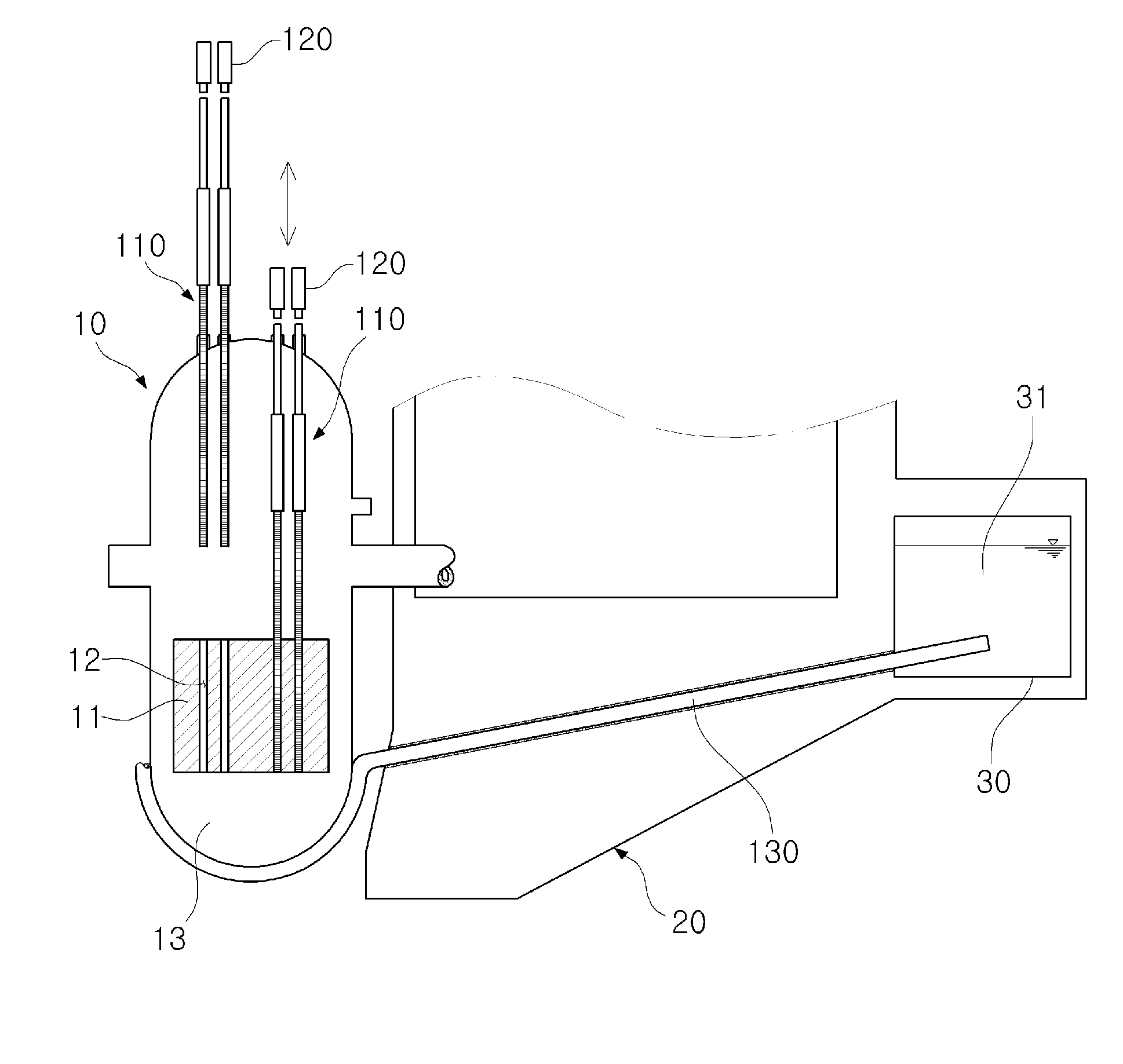
[0033]First, a decay heat removal system with a hybrid heat pipe having a neutron absorber and a coolant for cooling reactor core (hereinafter, referred to as a ‘decay heat removal system’) according to the present invention will be described with reference to FIG. 1.

[0034]According to the first exemplary embodiment, the decay heat removal system for cooling the nuclear power plant is installed in a nuclear reactor vessel 10, and removes decay heat of a reactor core 11 arranged in the reactor vessel 10. As shown in FIG. 1, the decay heat removal system for cooling a reactor core includes a first heat pipe 110, a control rod drive mechanism 120 and a second heat pipe 130.

[0035]The first heat pipe 110 is a cooling means inserted in the reactor core 11 arranged inside the reactor vessel 10 and directly removing the decay heat generated from the reactor core 11. Further, the first heat pipe 110 is placed above the reactor vessel 10 and arranged in upward and downward directions so as to...

second embodiment

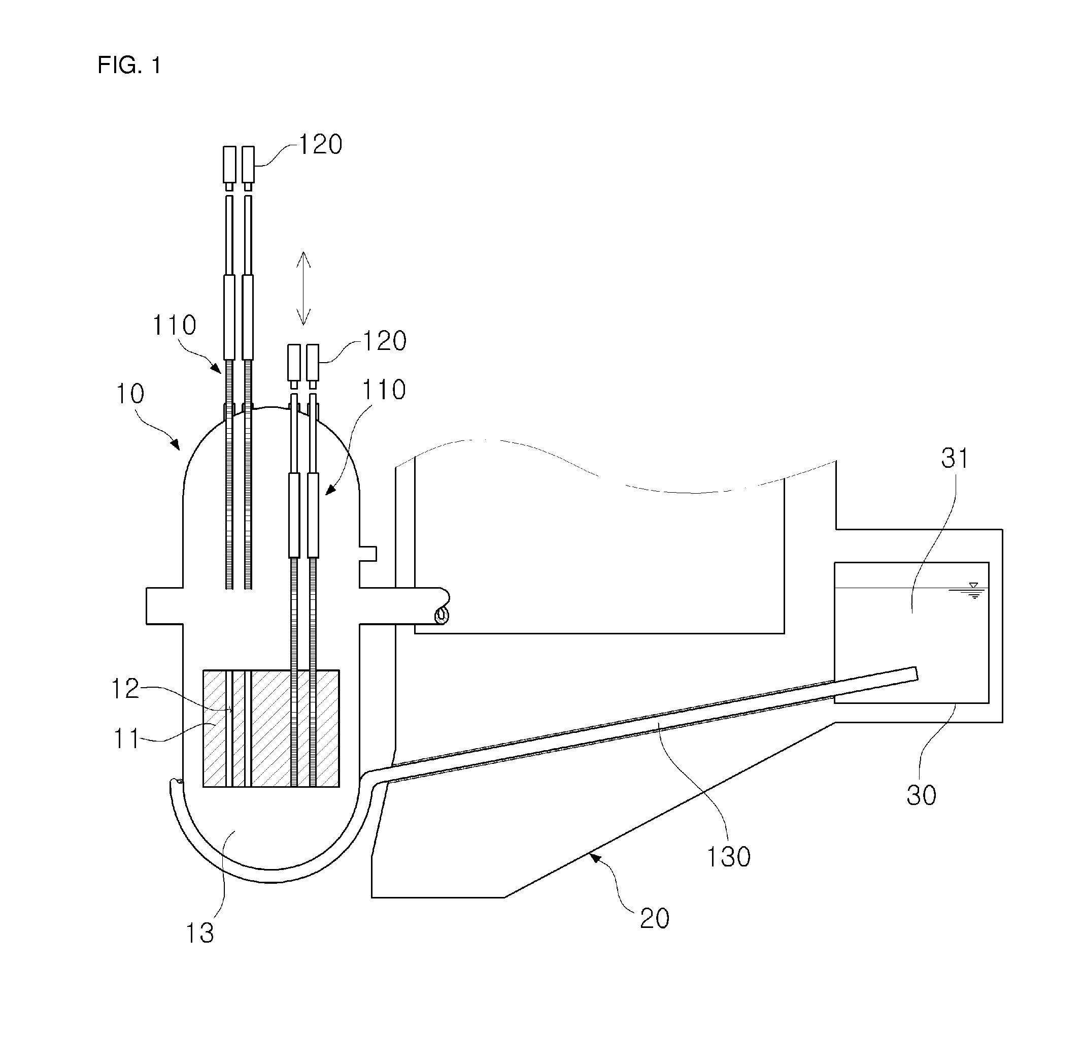
[0053]Next, elements and functions of a decay heat removal system 40 for cooling the spent fuel according to the present invention will be described with reference to FIG. 2.

[0054]Referring to FIG. 2, the decay heat removal system 40 for cooling the spent fuel assemblies according to the second embodiment of the present invention is a cooling system for removing the decay heat of the spent nuclear fuel assemblies 41. As shown in FIG. 2, the decay heat removal system 40 has a plurality of unit storage racks 200 that includes a plurality of standing heat pipe plates 210 coupled to one another and assembled in the form of a box to thereby internally form a nuclear fuel storage 220 for storing the spent nuclear fuel assemblies 41, in which the working fluid is circulated inside the heat pipe plate 210 and absorbs the decay heat of the spent nuclear fuel assemblies 41.

[0055]Here, the respective unit storage racks 200 are arranged and close to each other in the storage space where the coo...

third embodiment

[0060]Next, elements and functions of a decay heat removal system 50 for cooling a nuclear power plant according to the present invention will be described.

[0061]Like the foregoing decay heat removal system 40 for cooling spent fuel assemblies according to the second embodiment, the decay heat removal system 50 for cooling the spent fuel assemblies according to the third embodiment of the present invention is a cooling system for removing the decay heat of the spent fuel assemblies 41. As shown in FIG. 3, the decay heat removal system 50 includes a storage container 51, a fourth heat pipe 310 and, a fifth heat pipe 320.

[0062]The storage container 51 is a container internally formed with a storage space for storing the spent fuel assemblies 41 and placing each heat pipe 310, 320, 330 therein. Further, the coolant for removing the decay heat of the spent fuel assemblies 41 may be supplied to and stored in the storage container 51.

[0063]The fourth heat pipe 310 is a cooling means arran...


PUM


Abstract

Disclosed is a decay heat removal system for cooling the decay heat of a reactor core and the spent fuel. The decay heat removal system including: a first heat pipe which is placed in an upper plenum of the reactor vessel and arranged in upward and downward directions corresponding to a position of an insertion hole formed on a top of the nuclear fuel assemblies; a control rod drive mechanism which is connected to an upper portion of the first heat pipe and drives the first heat pipe to move up and down so that the first heat pipe can be selectively inserted in a control rod insertion hole of the reactor core arranged in the nuclear reactor vessel; and a second heat pipe which is coupled to and in close contact with a bottom surface of the reactor vessel and removes the decay heat generated in the reactor core.

Description

CROSS-REFERENCE TO RELATED APPLICATION[0001]This application claims priority to and the benefit of Korean Patent Application No. 10-2013-0084657 filed in the Korean Intellectual Property Office on Jul. 18, 2013, the entire contents of which are incorporated herein by reference.BACKGROUND OF THE INVENTION[0002](a) Field of the Invention[0003]The present invention relates to a decay heat removal system for cooling a nuclear power plant, and more particularly to a decay heat removal system with a hybrid heat pipe having a neutron absorber and a coolant for cooling a reactor core, which is installed in a nuclear reactor vessel, a nuclear fuel storage facility or the like nuclear power plant, and the hybrid heat pipe having the neutron absorber and the coolant is used to remove decay heat of a reactor core arranged in a nuclear reactor vessel or remove decay heat of spent fuel.[0004](b) Description of the Related Art[0005]In general, when an accident occurs in a nuclear reactor, a coolan...

Claims


Application Information

Patent Timeline
IPC IPC(8): G21C15/18
CPCG21C7/103G21C15/18G21C19/08G21C15/26G21C19/07G21C7/12Y02E30/30G21C15/257
Inventor BANG, IN CHEOLKIM, JI HYUNPARK, SEONG DAEKANG, SARAHSEO, HANKIM, KYOUNG-MOMOON, SUNG BOSEO, SEOK BINKIM, IN GUKJEONG, YEONG SHINHEO, HYO
Owner UNIST ULSAN NAT INST OF SCI & TECH
Learn More