Ultrasound signal processing device, ultrasound signal processing method, and non-transitory computer-readable recording medium

a processing device and ultrasound technology, applied in the field of ultrasonic signal transmission and reception processing, can solve the problems of deteriorating loss of code shape of rf signals, and notable decrease in amplitude of a main lobe, so as to prevent deterioration in the quality of decoded signals and suppress memory size

Active Publication Date: 2015-01-22
KONICA MINOLTA INC
View PDF3 Cites 5 Cited by
  • Summary
  • Abstract
  • Description
  • Claims
  • Application Information

AI Technical Summary

Benefits of technology

[0009]The present invention aims to provide an ultrasound signal processing device capable of suppressing increase in memory size while avoiding deterioration in quality of decoded signals. The above aim is achieved by an ultrasound signal processing device that outputs a plurality of code sequences to the transducer element array to cause the transducer element array to transmit ultrasound and receive reflected ultrasound, the code sequences each having a different arrangement of a plurality of code words, the ultrasound signal processing device comprising: M preceding decoders that obtain N convolution signals by convolving each of N transducer element...

Problems solved by technology

The code shape of the RF signals is lost due to the delay-and-sum on the RF signals in coded form, and there occurs a notable...

Method used


Image

  • Ultrasound signal processing device, ultrasound signal processing method, and non-transitory computer-readable recording medium
  • Ultrasound signal processing device, ultrasound signal processing method, and non-transitory computer-readable recording medium
  • Ultrasound signal processing device, ultrasound signal processing method, and non-transitory computer-readable recording medium

Examples


embodiment

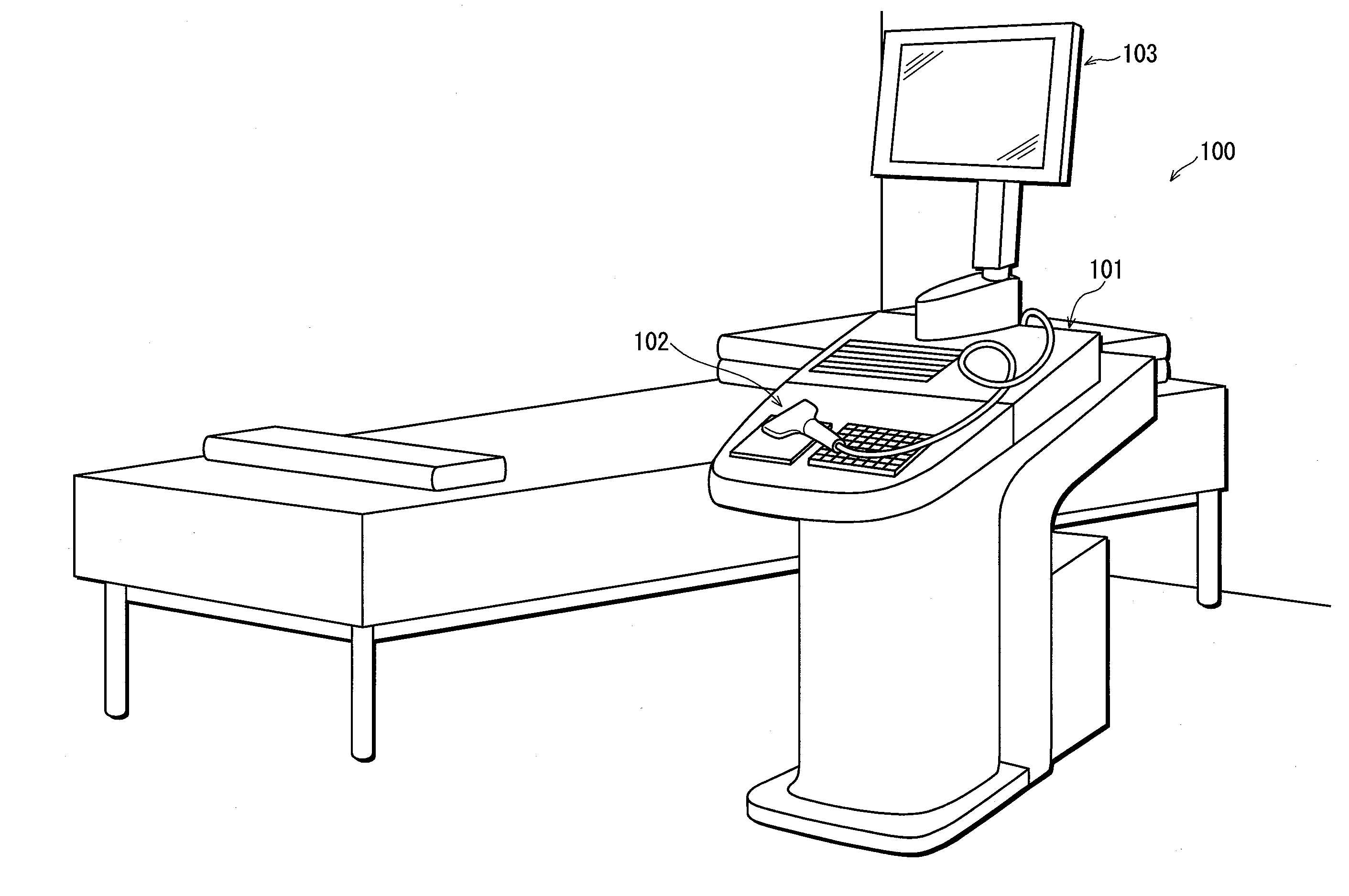
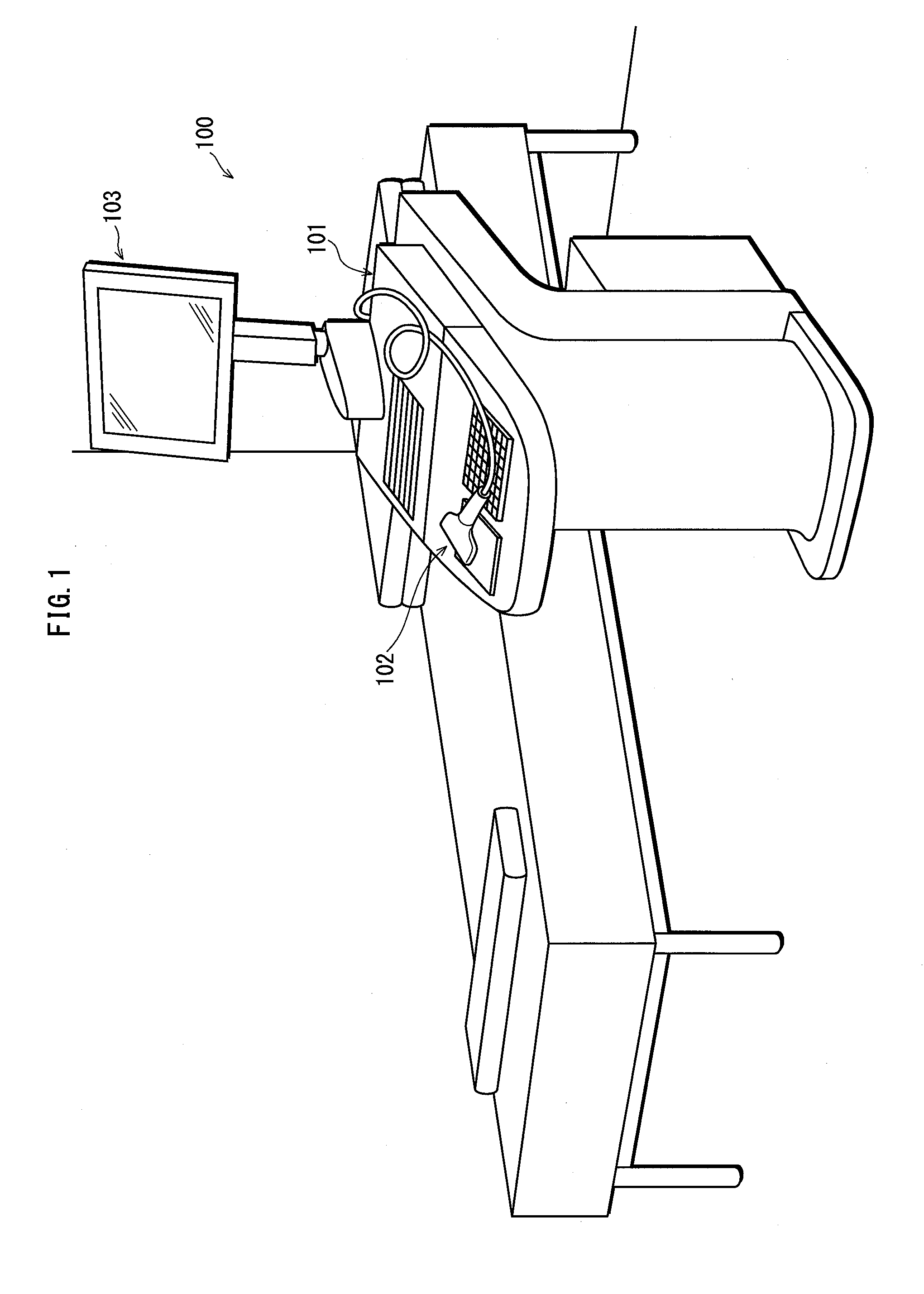
[0031]The following describes a schematic structure of an ultrasound signal processing device relating to the present embodiment. FIG. 1 shows an outer appearance structure of an ultrasound diagnostic system including an ultrasound signal processing device.

[0032]An ultrasound diagnostic system 100 includes an ultrasound signal processing device 101, an ultrasound probe 102, and a display unit 103.

[0033]The ultrasound signal processing device 101 performs transmission and reception of ultrasound signals and image formation of the received ultrasound signals in order to perform ultrasound diagnosis.

[0034]The ultrasound probe 102 includes therein a transducer element array, and transmits ultrasound and receives a reflected ultrasound signal that is reflected from a subject. The transducer element array is composed of a plurality of transducer elements 110. A reflected ultrasound wave which reflected off a reflection point spherically spreads to reach the transducer elements which are t...


PUM


Abstract

Preceding decoders each convolve a corresponding one of a plurality of transducer elements constituting a transducer element array of an ultrasound probe with an impulse response waveform, while varying a filter coefficient corresponding to time side lobes for each transmission event. A succeeding decoder stores, in a memory, a reception beam signal that is output from a reception beam former. When a new reception beam signal is output, the succeeding decoder performs delay-and-sum on the new reception beam signal and the reception beam signal, which has been output immediately before the new reception beam signal and is stored in the memory.

Description

[0001]This application is based on an application No. 2013-147249 filed in Japan on Jul. 16, 2013 and an application No. 2014-142955 filed in Japan on Jul. 11, 2014, the contents of which are hereby incorporated by reference.BACKGROUND OF THE INVENTION[0002](1) Field of the Invention[0003]The present invention belongs to a technical field of ultrasound signal transmission and reception processing, and particularly relates to decoding of code sequences coded by pulse compression.[0004](2) Description of the Related Art[0005]According to ultrasound signal transmission and reception processing, transmission signals for transducer elements constituting an ultrasound probe are generated, and also delay-and-sum is performed on each of respective reception signals output from the transducer elements by a reception beam former so as to obtain a reception beam signal to generate an ultrasound echo signal. A pixel array corresponding to one line of an ultrasound image for ultrasound diagnosis...

Claims


Application Information

Patent Timeline
IPC IPC(8): A61B5/00A61B8/08
CPCA61B5/7228A61B8/5207A61B8/0891G01S7/52047G01S15/8915G01S15/8961
Inventor SUSUMU, YASUAKI
Owner KONICA MINOLTA INC
Why Eureka
Try Eureka