System and method of controlling heat input in tandem hot-wire applications

a technology of tandem hot-wire and heat input, which is applied in the field of tandem hot-wire systems, can solve the problems of inability to sustain micro-arcs, and achieve the effects of increasing heat input, increasing agitation of molten puddles, and high intensity energy

Active Publication Date: 2015-01-29
LINCOLN GLOBAL INC
View PDF1 Cites 15 Cited by
  • Summary
  • Abstract
  • Description
  • Claims
  • Application Information

AI Technical Summary

Benefits of technology

[0005]Exemplary embodiments of the present invention include systems and methods in which current waveforms of at least one power supply is varied to achieve a desired heat input in order to optimize processes such as, e.g., welding, joining, cladding, building-up, brazing, etc. In some embodiments, the system includes a high intensity energy source to create a molten puddle on a surface of a workpiece and a wire feeder that feeds a wire to the molten puddle via a contact tube. The system also includes a hot-wire power supply that outputs a first heating current during a first mode of operation and a second heating current during a second mode of operation. The hot-wire power supply provides the first heating current or the second heating current to the wire via the contact tube. The system further includes a controller that initiates the first mode of operation in the hot-wire power supply to heat the wire to a desired temperature and then switches the hot-wire power supply from the first mode of operation to the second mode of operation to create a micro-arc, which is created between the wire and the work

Problems solved by technology

The micro-arc is extinguished when the output of the hot-wire power supply is t

Method used


Image

  • System and method of controlling heat input in tandem hot-wire applications
  • System and method of controlling heat input in tandem hot-wire applications
  • System and method of controlling heat input in tandem hot-wire applications

Examples


Embodiment Construction

[0020]Exemplary embodiments of the invention will now be described below by reference to the attached Figures. The described exemplary embodiments are intended to assist the understanding of the invention, and are not intended to limit the scope of the invention in any way. Like reference numerals refer to like elements throughout.

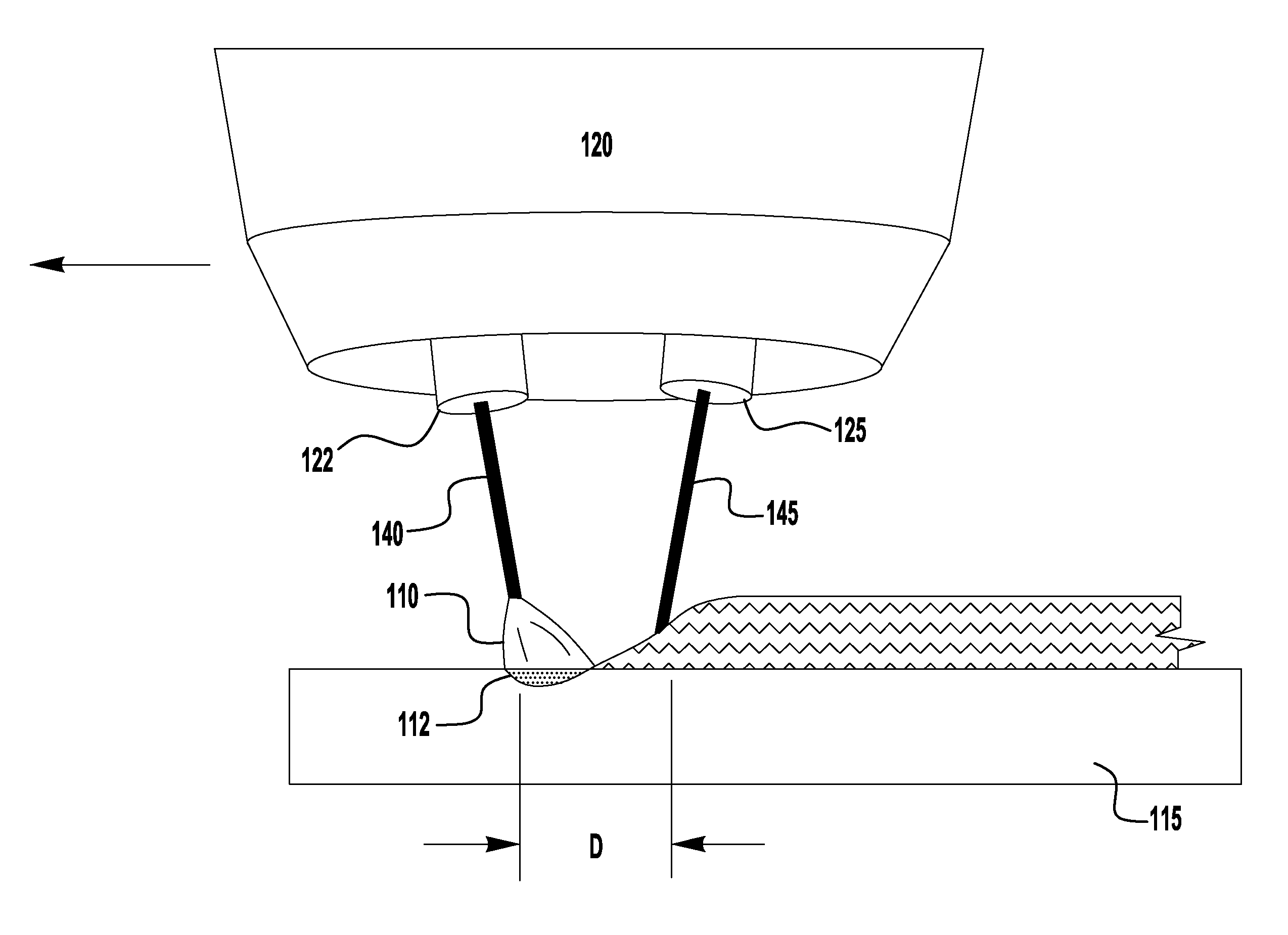
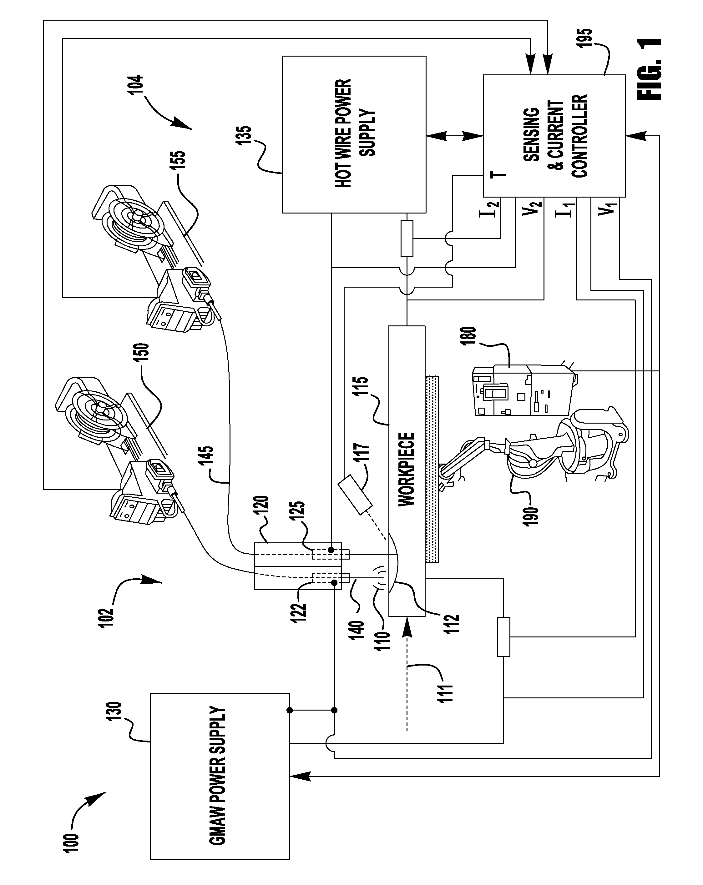
[0021]An exemplary embodiment of this is shown in FIG. 1, which shows a system 100. The system 100 illustrates a tandem hot wire configuration that includes a high intensity energy system 102 and a hot wire system 104. The high intensity energy system 102, which in the exemplary embodiment of FIG. 1 is configured as a GMAW system, heats the workpiece 115 to create a molten puddle 112, i.e., a weld puddle. Although the high intensity energy system 102 is illustrated as a GMAW system, the present invention is not limited to this exemplary embodiment and, in other exemplary embodiments, the high intensity energy system 102 can be a TIG, PAW, Laser Welding, FC...


PUM

PropertyMeasurementUnit
Timeaaaaaaaaaa
Timeaaaaaaaaaa
Electrical resistanceaaaaaaaaaa

Abstract

A system and method is provided. The system includes a high intensity energy source to create a molten puddle on a surface of a workpiece and a wire feeder that feeds a wire to the molten puddle via a contact tube. The system also includes a power supply that outputs a first heating current during a first mode of operation and a second heating current during a second mode of operation. The system further includes a controller that initiates the first mode of operation in the power supply to heat the wire to a desired temperature and switches the power supply from the first mode of operation to the second mode of operation to create a micro-arc. The second mode of operation provides at least one of an increased heat input to the molten puddle and an increased agitation of the molten puddle relative to the first mode of operation.

Description

BACKGROUND OF THE INVENTION[0001]1. Field of the Invention[0002]Systems and methods of the present invention relate to welding, joining, cladding, building-up, and brazing applications, and more specifically to tandem hot-wire systems.[0003]2. Description of the Related Art[0004]As advancements in welding have occurred, the demands on welding throughput have increased. Because of this, various systems have been developed to increase the speed of welding operations, including systems which use multiple welding power supplies in which one power supply is used to create an arc in a consumable electrode to form a weld puddle and a second power supply is used to heat a filler wire in the same welding operation. While these systems can increase the speed or deposition rate of a welding operation, the power supplies are limited in their function and ability to vary heat input in order to optimize the process such as, e.g., welding, joining, cladding, building-up, brazing, etc. Thus, improv...

Claims


Application Information

Patent Timeline
IPC IPC(8): B23K9/09
CPCB23K9/091B23K9/092B23K9/1043B23K9/122B23K9/125B23K9/1735
Inventor PETERS, STEVEN R.
Owner LINCOLN GLOBAL INC
Why Eureka
Try Eureka