Compound Elliptical Reflector for Curing Optical Fibers

a technology of optical fibers and reflectors, applied in the field of compound elliptical reflectors for curing optical fibers, can solve the problems of lowering curing and production rates, irradiating optical fiber surfaces, and unable to cure uniformity, so as to achieve high data transmission rates, maintain long-term durability in performance, and be flexible

Active Publication Date: 2015-01-29
PHOSEON TECHNOLOGY INC
View PDF3 Cites 46 Cited by
  • Summary
  • Abstract
  • Description
  • Claims
  • Application Information

AI Technical Summary

Benefits of technology

[0001]Optical fibers are used ubiquitously in lighting and imaging applications, as well as in the telecommunication industry, where they provide higher data transmission rates over longer distances as compared to electric wiring. In addition, optical fibers are more flexible, lighter, and can be drawn into thinner diameters than metal wiring, allowing for higher-capacity bundling of fibers into cables. Surface coatings, applied via an ultra-violet (UV) curing process, are employed to protect optical fibers from physical damage and moisture intrusion, and to maintain their long-term durability in performance.

Problems solved by technology

Curing uniformity issues can arise due to imprecise alignment of the optical fiber relative to the light source, or an irregular-shaped optical fiber.
Namely, by displacing the UV light source and the optical fiber away from the focal points of the elliptical reflector, the intensity of UV light irradiating the optical fiber surfaces is dispersed and reduced, thereby lowering the curing and production rates, and imparting higher manufacturing costs.

Method used


Image

  • Compound Elliptical Reflector for Curing Optical Fibers
  • Compound Elliptical Reflector for Curing Optical Fibers
  • Compound Elliptical Reflector for Curing Optical Fibers

Examples


Embodiment Construction

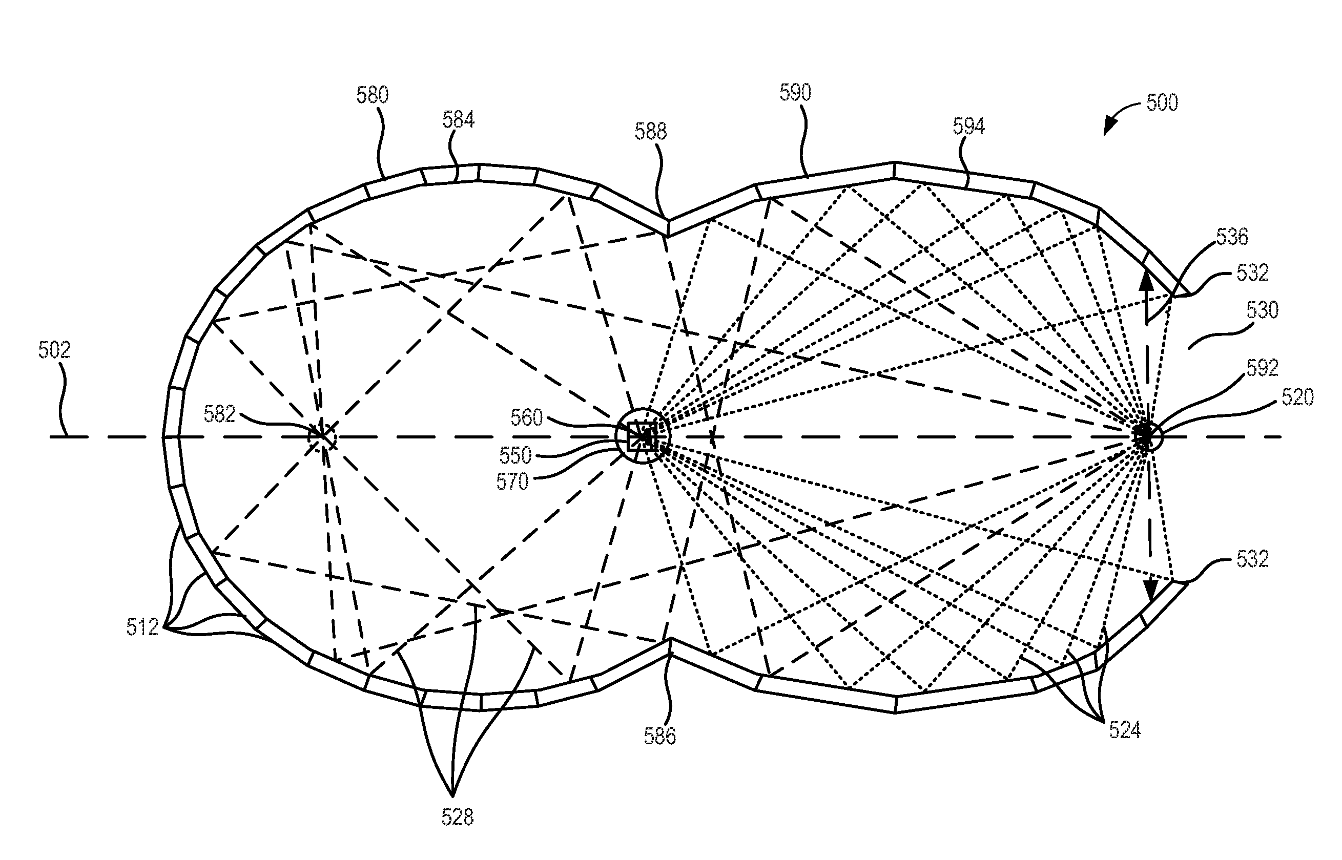
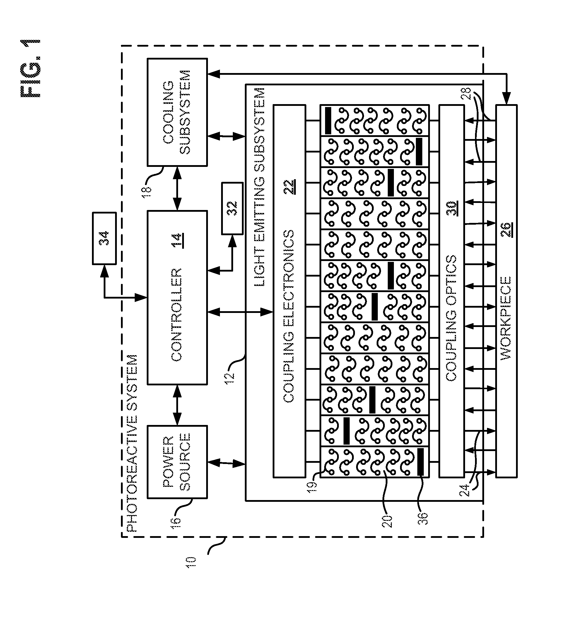
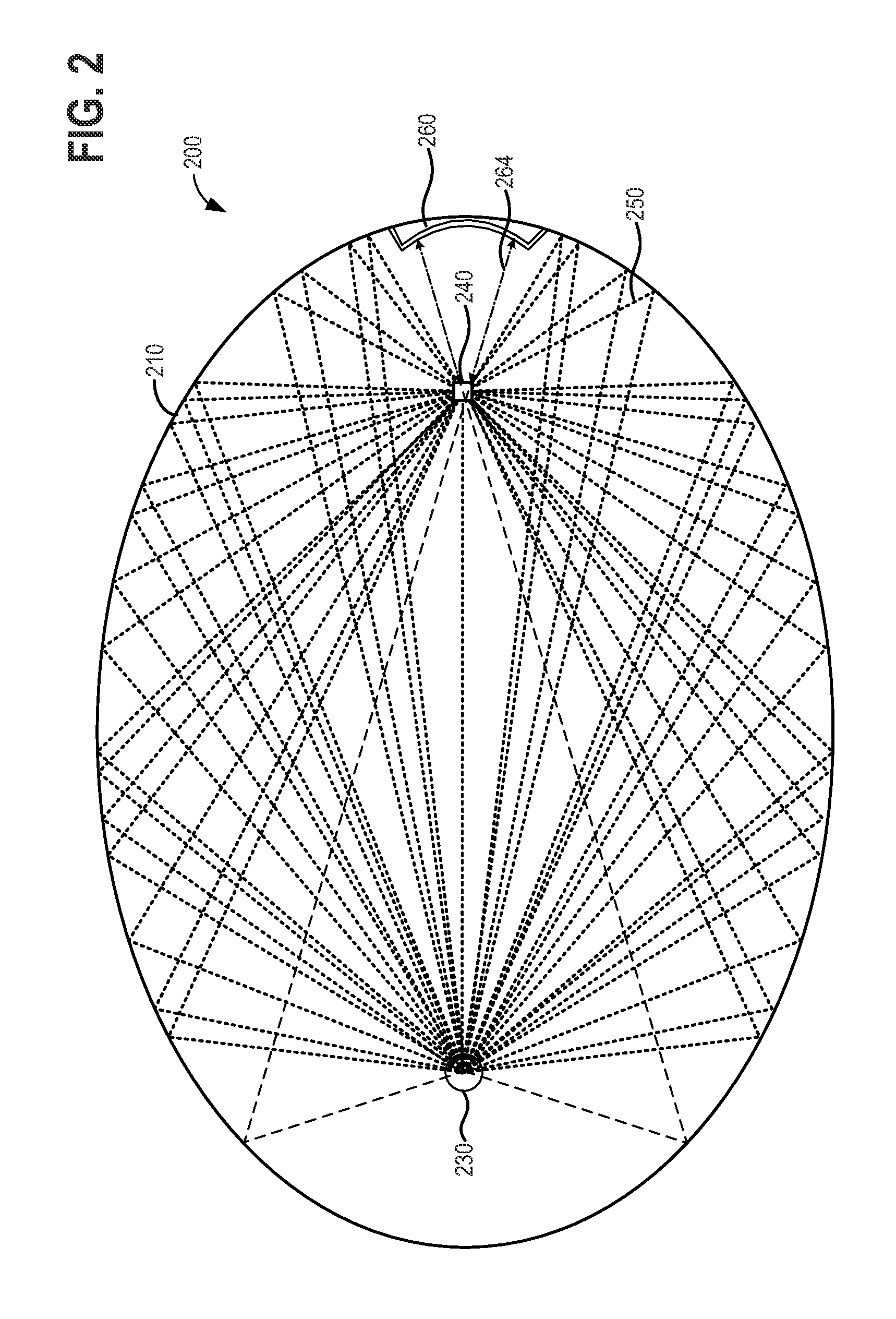
[0017]The present description is for a UV curing device, method and system for use in manufacturing coated optical fibers, ribbons, cables, and other workpieces. Optical fiber coatings may be UV-cured via a UV curing device employing dual elliptical reflectors arranged to have a co-located focus, wherein the workpiece (e.g., the optical fiber) is positioned at the co-located focus, and two UV light sources are located at the second focus of each elliptical reflector. FIG. 1 illustrates an example of a photoreactive system, comprising a power source, a controller, and a light-emitting subsystem. FIG. 2 shows a single elliptical reflector coupling optics configuration of a conventional UV curing device. FIG. 3 illustrates an example of two elliptical surfaces arranged to have a co-located focus. FIGS. 4-6 illustrate dual elliptical reflector coupling optics configurations for a UV curing device, wherein the dual elliptical reflectors have a co-located focus. FIG. 7-8 are cross-section...


PUM


Abstract

A curing device comprises a first elliptic cylindrical reflector and a second elliptic cylindrical reflector, the first elliptic cylindrical reflector and the second elliptic cylindrical reflector arranged to have a co-located focus, and a light source located at a second focus of the first elliptic cylindrical reflector, wherein light emitted from the light source is reflected to the co-located focus from the first elliptic cylindrical reflector and retro-reflected to the co-located focus from the second elliptic cylindrical reflector.

Description

BACKGROUND AND SUMMARY[0001]Optical fibers are used ubiquitously in lighting and imaging applications, as well as in the telecommunication industry, where they provide higher data transmission rates over longer distances as compared to electric wiring. In addition, optical fibers are more flexible, lighter, and can be drawn into thinner diameters than metal wiring, allowing for higher-capacity bundling of fibers into cables. Surface coatings, applied via an ultra-violet (UV) curing process, are employed to protect optical fibers from physical damage and moisture intrusion, and to maintain their long-term durability in performance.[0002]Carter et al. (U.S. Pat. No. 6,626,561) addresses UV curing uniformity issues for optical fibers having surfaces that are located outside a focal point of a UV curing device employing an elliptical reflector to direct UV light from a single UV light source positioned at a second focal point of the elliptical reflector, to the surface of the optical fi...

Claims


Application Information

Patent Timeline
Patent Type & Authority Applications(United States)
IPC IPC(8): H05B3/00
CPCH05B3/0038B05D3/067B05D7/546F26B3/28
Inventor CHILDERS, DOUG
Owner PHOSEON TECHNOLOGY INC
Why Eureka
Try Eureka