Tool shank

a tool shank and tool technology, applied in the field of tool shanks, can solve the problems of vibration and damage of bbt shanks 24/b>, and deteriorating precision of machining processes, so as to enhance the structural strength of the present invention during the machining process and improve the reliability of machining

Inactive Publication Date: 2015-01-29
CHEN FENG TIEN
View PDF12 Cites 8 Cited by
  • Summary
  • Abstract
  • Description
  • Claims
  • Application Information

AI Technical Summary

Benefits of technology

[0004]Therefore, a novel tool shank is provided herein capable of tightly and reliably joining to the spindle of a machine tool with superior robustness even when the machine tool is operated under a high speed.
[0010]The advantages of the present invention are as follows. The slightly outward bulges defined by the slits increase the contact area with the tapered socket of a spindle, thereby avoiding the gaps happened in the prior arts. As such, a tool is tightly jointed to the spindle during its high-speed rotation without causing vibration. On the other hand, due to the increased contact area to the tapered socket, the structural strength of the present invention during machining process is enhanced and as such the present invention is prevented from being damaged by a lateral external force, thereby achieving the machining reliability.

Problems solved by technology

The precision of the machining processes is therefore deteriorated.
Again, this would cause the BBT shank 24 to vibrate and get damaged.
The precision of the machining processes is also deteriorated.

Method used


Image

  • Tool shank
  • Tool shank
  • Tool shank

Examples


first embodiment

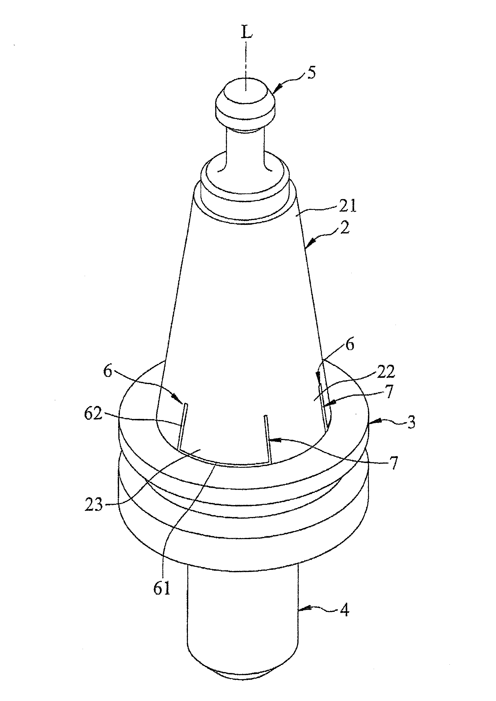
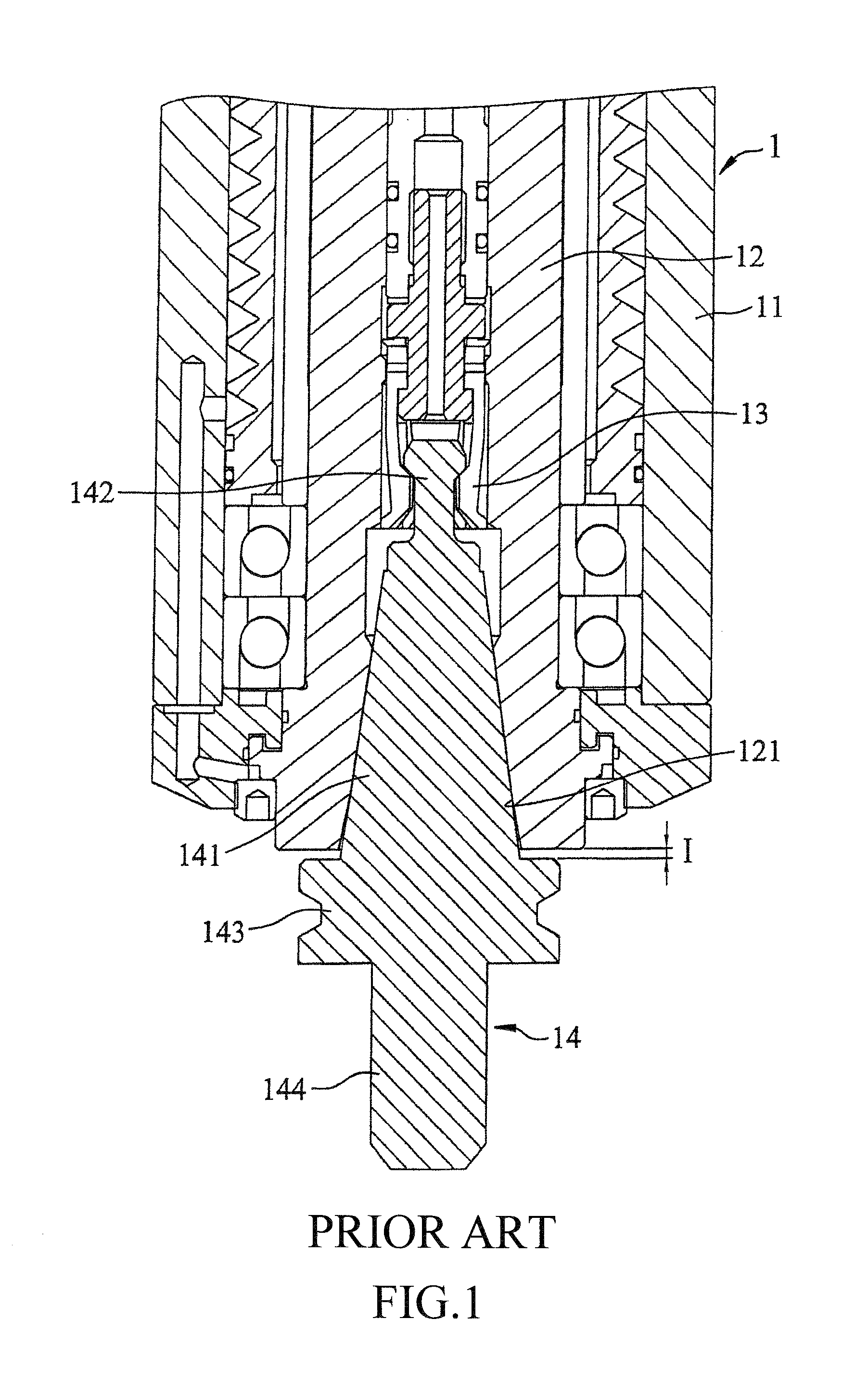
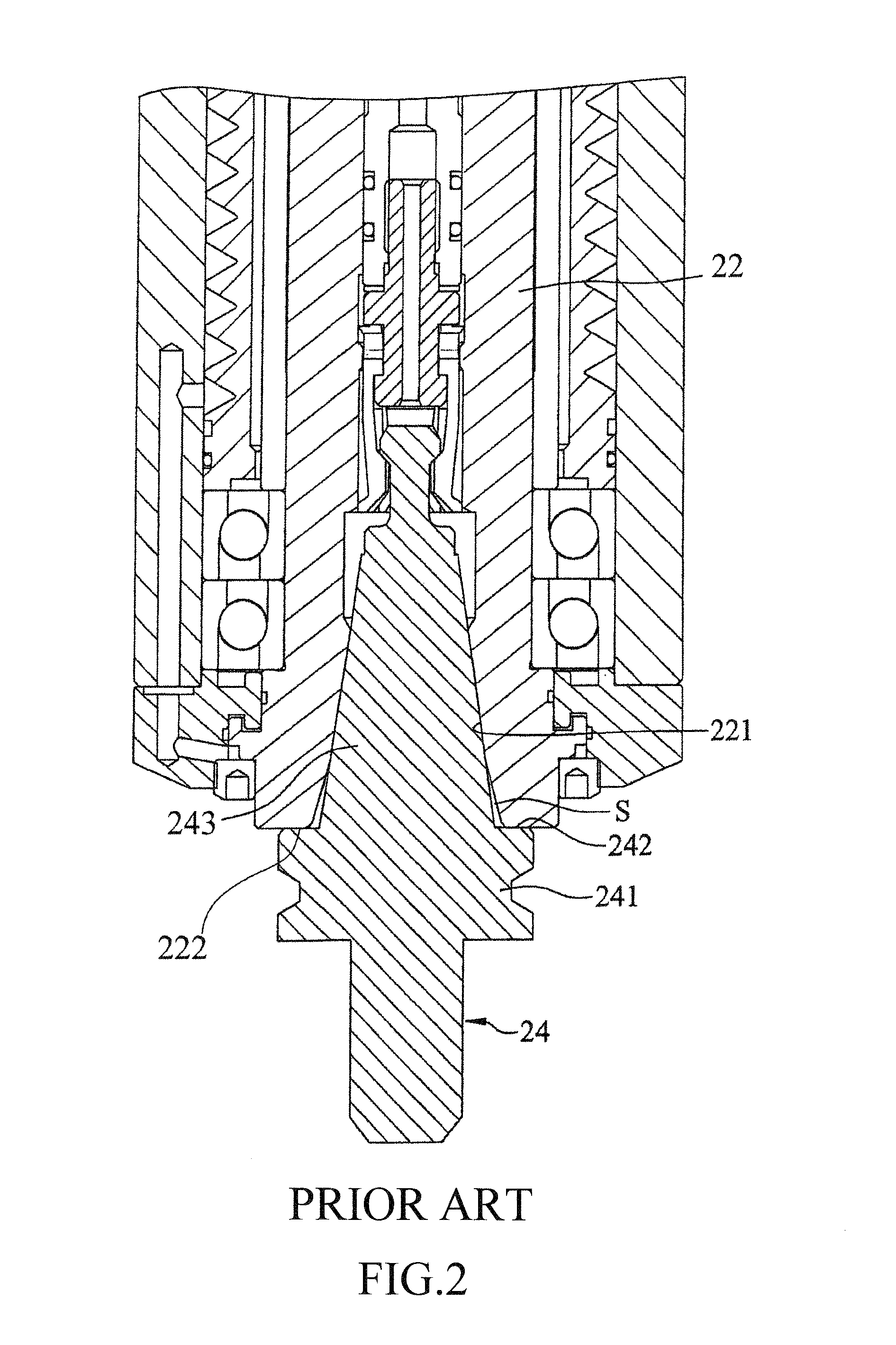
[0026]As shown in FIGS. 3, 4, and 8, a tool shank according to the present invention is installed on a spindle assembly 100. The spindle assembly 10 contains a casing 10, a spindle 20 in the casing 10 capable of high-speed rotation, and a clamper 30 inside the spindle 20 capable of vertical movement. The spindle 20 has a tapered socket 201 adjacent to a bottom end of the spindle 20. The tool shank of the present embodiment contains a taper member 2, a flange member 3, a clamped member 5, a holder member 4, a number of slits 6, and a number of flexible layers 7.

[0027]The taper member 2 is detachably mounted to the tapered socket 201 and has a conic shape that is narrowed to a top end and is broadened to a bottom end along an axial direction L. The taper member 2 therefore has a top section 21 of a smaller diameter and a bottom section 22 of a larger diameter.

[0028]The flange member 3 is beneath the bottom section 22 of the taper member 2 and has a greater diameter than that of the bo...

second embodiment

[0035]the present invention is similar to the previous first embodiment except that a step surface 31 is formed on a top side of the flange member 3. In an application scenario shown in FIGS. 9 and 10, the present invention works as a BBT shank. As illustrated, when the taper member 2 is plugged into the tapered socket 201 of the spindle assembly 100, the taper member 2 is tightly joined to the tapered socket 201 and no gap is left between the tapered socket 201 and the taper member 2. Therefore, the spindle 20 can spin in an even higher speed without causing vibration, thereby enhancing the machining reliability and precision.

third embodiment

[0036]the present invention as shown in FIGS. 11 and 12 differs from the previous embodiments as follows.

[0037]Each slit 6 contains an inwardly indented lateral segment 61 perpendicular to the axial direction L on the bottom section 22, and two vertical segments 62 extended from the lateral segment 61's two ends towards the flange member 3.

[0038]The tool shank of the present invention has the following advantages.

[0039]Firstly, the slightly outward bulges 23 defined by the slits 6 increase the contact area with the tapered socket 201 of a spindle 20, thereby avoiding the gaps happened in the prior arts. As such, a tool is tightly jointed to the spindle 20 during its high-speed rotation without causing vibration, thereby enhancing the machining precision.

[0040]Secondly, due to the increased contact area to the tapered socket 201, the structural strength of the present invention during machining process is enhanced and as such the present invention is prevented from being damaged by a...


PUM

PropertyMeasurementUnit
diameteraaaaaaaaaa
flexibleaaaaaaaaaa
speedaaaaaaaaaa

Abstract

The tool shank contains a taper member, a flange member, a holder member, a clamped member, and a number of slits. The taper member has a conic shape extended along an axial direction with a top section and a bottom section. The flange member is beneath the bottom section of the taper member. The holder member is extended downward from a bottom side of the flange member along the axial direction. The clamped member is extended upward from the top section of the taper member. The slits are configured at intervals around the bottom section surrounding the axial direction. Each slit defines a slightly outwardly bulge. The bulges increase the contact area with and avoid gaps to a tapered socket of a spindle. As such, the tool shank is tightly jointed to the spindle during high-speed rotation without causing vibration and damage.

Description

TECHNICAL FIELD OF THE INVENTION[0001]The present invention is generally related to machine tools, and more particular to a shank for fitting a tool to the spindle of a machine tool.DESCRIPTION OF THE PRIOR ART[0002]FIG. 1 shows a conventional BT shank 14 installed on a spindle assembly 1 of a CNC machine tool. The spindle assembly 1 contains a casing 11, a spindle 12 in the casing 11 capable of high-speed rotation, and a clamper 13 inside the spindle 20 capable of vertical movement. The spindle 12 has a tapered socket 121 adjacent to a bottom end of the spindle 12 for receiving the BT shank 14. The BT shank 14 contains a cone-shaped taper member 141, a clamped member 142 extended from the taper member 141, a flange member 143 beneath the taper member 141, and a holder member 144 extended downward from the flange member 143 for installing a tool (not shown). The taper member 141 is plugged into the tapered socket 121 and the BT shank 14 is further secured by the clamper 13 clamping ...

Claims


Application Information

Patent Timeline
Patent Type & Authority Applications(United States)
IPC IPC(8): B23B31/00
CPCB23B31/006B23B2231/0292B23B2231/0284B23B29/022B23B2231/0272B23B2231/0288B23B2250/16B23B2270/06B23Q3/12Y10T279/17965Y10T409/304312Y10T409/30952
Inventor CHEN, FENG-TIEN
Owner CHEN FENG TIEN
Why Eureka
Try Eureka