
Sandwich type load bearing panel

Inactive Publication Date: 2015-01-29
AIRBUS HELICOPTERS DEUT GMBH
View PDF4 Cites 26 Cited by
  • Summary
  • Abstract
  • Description
  • Claims
  • Application Information

AI Technical Summary

Benefits of technology

The patent is for an invention that improves the strength and weight efficiency of composite load bearing panels or shells. It provides a structural sandwich element with high stiffness and strength capabilities, especially bending stiffness. The invention also enables the implementation of additional damping mechanisms and noise attenuating characteristics, and is especially suited for automatic fiber placement techniques.

Problems solved by technology

Reaching an optimal weight efficiency of composite sandwich panels or shells is often limited by a minimum feasible cover skin thickness which is a function of the minimum available ply thickness and a laminate lay-up configuration, often tailored to be more or less isotropic.
Moreover, the damage tolerance of typical composite sandwich panels is known to have the risk of delaminations propagating all along the continuous core / skin interface.
The acoustic damping behavior of typical composite sandwich panels is known to be insufficient.
Some main disadvantages are related to those typical arrangements of composite sandwich panels:
Too small cover sheet thicknesses reduce however the strength-to-weight ratio—especially when using honeycomb cores—as well as the damage tolerance capabilities.
Too large core thicknesses still further reduce the strength capabilities of the cover sheets, especially for honeycomb cores.
Here, the maximum weight efficiency of a sandwich design often cannot be exploited due to the limitations imposed by the minimum feasible thickness of the cover sheets.
The damage resistance and the damage tolerance of sandwich panels with continuous cover sheets are deficient.
The possibilities offered by automatic processes like Automatic Fiber Placement are not fully exploited when focusing on standard sandwich arrangements.
The high stiffness-to-weight ratio of sandwich panels imparts superior noise transmission and hence a deficient noise insulation capability.
The acoustic damping behavior of typical sandwich arrangements is deficient, hence leading to low transmission loss factors.
The manufacturing of those skins is only feasible with winding techniques using a separate pre-curing of the skins.
A co-curing process of these composite sandwich panels of the state of the art, i.e. simultaneous curing of both sandwich panel skins with the core, would not be suitable, since large “telegraphing” would develop hence leading to a considerable performance reduction of these composite sandwich panels of the state of the art.
Moreover, a local tailoring of the mesh of these composite sandwich panels of the state of the art is only feasible by locally adding extra plies.
Grid structures tend to be more effective in-plane and less effective out-of-plane in terms of stiffness in comparison to sandwich structures.
Such a skin tends however to buckle at relatively low load levels and adds additional structural weight.
Typical grid designs are not compatible with conventional fiber placement techniques.
Typical grid designs have crossing stiffeners with a rectangular cross section hence leading to a considerable excess of material within the intersections points leading either to excessive fiber volume fractions or to an unacceptable bulge formation at the intersection points.
Winded grids do not allow for a local change of the stiffeners cross-section.
The implementation of an additional skin is not easy, since there is an excess of material on each intersecting point of the intercrossing strips which leads to a variation in total panel thickness.
The placement of material within cavities is not necessarily suitable for conventional automatic fiber placement processes.
Moreover, the opened and free-standing sides of the honeycomb core are susceptible to environmental effects.
The honeycomb lattice arrangement requires intensive milling operations.
This requirement leads to difficult handling characteristics.
Hence, that design is considered not suitable for automatic lay-up processes.
The noise damping behavior of this composite sandwich lattice structure of the state of the art is not improved.
The implementation of additional damping mechanisms is not possible.
The design of this composite sandwich lattice structure of the state of the art is not suitable for structural shells enclosing a fuel tank region due to the numerous cavities of the opened lattice design.
Honeycombs as core materials are not addressed because they are not optimal in terms of heat and noise isolation.
This, again, shows that there is no mechanical, load-bearing link intended and realized between the meshed element and the flexible foil, as would be the case in a sandwich construction: the small surface of a rod is not enough to provide for a stiff link and the mechanical interaction to the core is poor.
Moreover, the bi-axiality of the mesh does not provide for sufficient in-plane shear stiffness, which is necessary for a structural element for aircraft applications.

Method used


Image

  • Sandwich type load bearing panel
  • Sandwich type load bearing panel
  • Sandwich type load bearing panel

Examples


Embodiment Construction

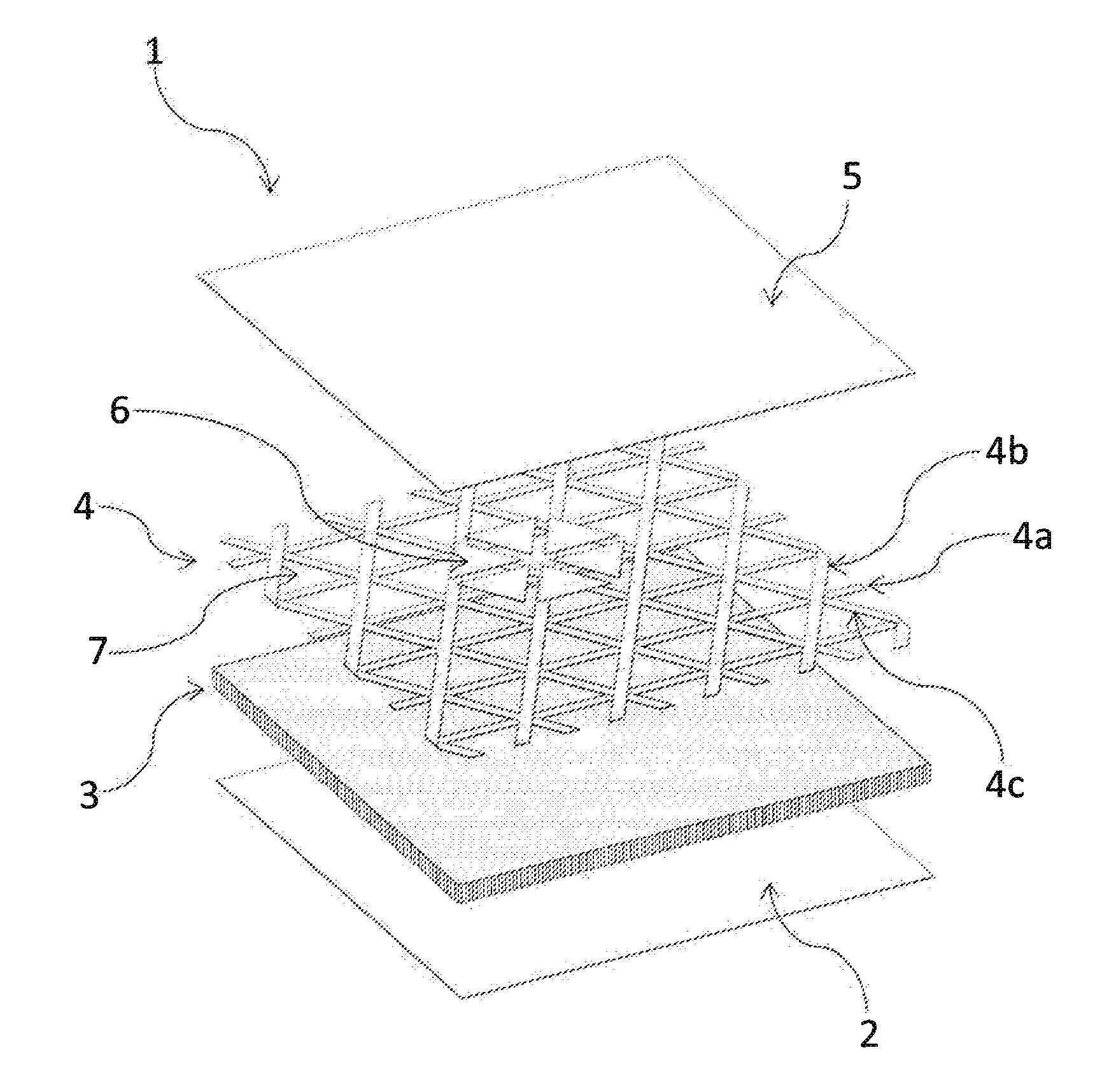
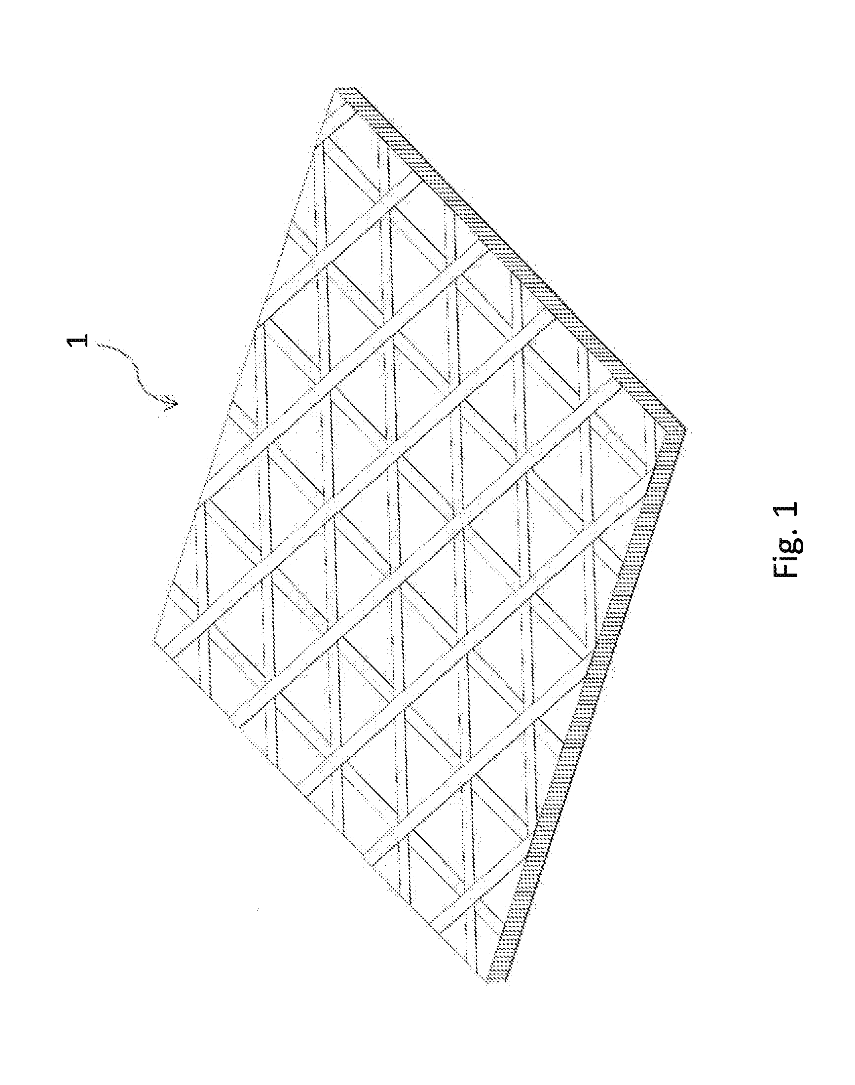
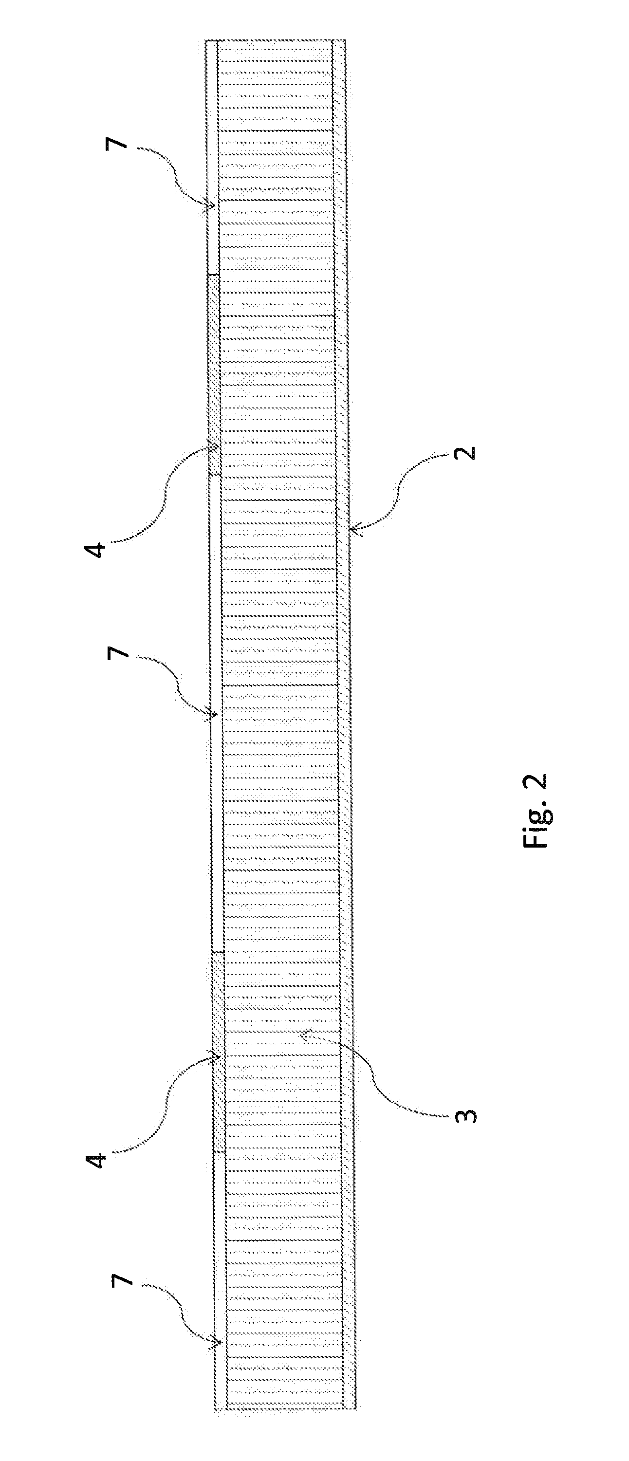
[0099]According to FIG. 1, 2 a sandwich type load bearing panel 1 comprises a shear stiff core 3 with two main surfaces opposed to each other. The shear stiff core 3 is made of a cellular material, such as a metallic or a composite honeycomb. The shear stiff core 3 has a uniform thickness, meaning either a constant thickness or a slightly variable thickness with thickness slopes less than 1 to 20, i.e. 1 mm in thickness per 20 mm in the plane along the interfaces of the strips with the one of the two main surfaces A first outer and a second inner composite layer 2, 4 are respectively bonded to one of the main surfaces of the core 3. The first outer composite layer 2 is continuous and monolithic. The second inner layer 4 is an open net of equal sized meshes with uncovered mesh pockets 7.

[0100]According to FIG. 3 corresponding features are referred to with the same references of FIG. 1, 2. The sandwich type load bearing panel 1 has the core 3 between the first outer continuous layer 2...


PUM

PropertyMeasurementUnit
Pressureaaaaaaaaaa
Massaaaaaaaaaa
Lengthaaaaaaaaaa

Abstract

A sandwich type load bearing panel (1) with a transversely shear stiff core (3) and a plurality of individual unidirectional plies respectively for a first and a second composite layer (2, 4), bonded each to one of the main surfaces of the core (3). The first composite layer (2) is a continuous and monolithic assembly and the second layer (4) is an open net of intercrossing strips (4a, 4b, 4c) running along at least three directions and being laid up of said plurality of individual unidirectional plies.

Description

CROSS REFERENCE TO RELATED APPLICATION[0001]This application claims priority to European patent application No. 13 400017.3 filed on Jul. 26, 2013, the disclosure of which is incorporated in its entirety by reference herein.BACKGROUND OF THE INVENTION[0002](1) Field of the Invention[0003]The invention relates to a sandwich type load bearing panel with the features of the preamble of claim 1.[0004](2) Description of Related Art[0005]In the following the term “sandwich type load bearing panel” is used with the supplemental meaning of sandwich type load bearing shell.[0006]Sandwich panels or sandwich shells are widely used for spacecraft and aircraft design for structural components such as fuselage shells, floor panels, wing covers and control surfaces. Sandwich panels or shells are typically built of three main constituents: two thin, strong and stiff continuous cover sheets adhesively bonded to each side of a thick core which is considerably weaker and less dense than the cover shee...

Claims


Application Information

Patent Timeline
IPC IPC(8): B32B3/12B32B3/30B32B5/02
CPCB32B3/12B32B5/028B32B2307/102B32B2250/03B32B2605/18B32B3/30G10K11/168B32B15/046B32B15/14B32B2262/0269B32B2262/101B32B2262/106B32B2307/542B29D99/0014E04C2/365Y10T428/24149B29D24/005B29C70/382B29C70/224
Inventor FINK, AXEL
Owner AIRBUS HELICOPTERS DEUT GMBH
Learn More