Power shift transmission

a transmission and power technology, applied in mechanical equipment, transportation and packaging, gearing, etc., can solve the problems of high manufacturing technology cost, inability to provide an additional operation mode, and two-stage power transmission, and achieve the effect of reducing manufacturing steps, simple design, and compact arrangemen

Active Publication Date: 2015-01-29
DEERE & CO
View PDF8 Cites 10 Cited by
  • Summary
  • Abstract
  • Description
  • Claims
  • Application Information

AI Technical Summary

Benefits of technology

[0006]In accordance with an aspect of the invention, a power shift transmission is designed so that, by means of a first shift element, the first output shaft can be connected to the output-side sun gear of the stepped planetary set, and, by means of a second shift element, the first output shaft can be directly connected to the input shaft, wherein the input-side sun gear of the stepped planetary set is non-rotatably connected to a housing part of the power shift transmission. The sun gears and the stepped planetary set are arranged in this manner so that as a result of the formation of three exchangeable gear sets of sun gears and stepped planetary set, at least four different operation modes can be operated, wherein in each case, in a formed gear set, two of the four operation modes can be operated by shifting the shift elements. Furthermore, an extremely compact arrangement is produced, which, in addition, can be manufactured using a simple design, since, inter alia, a hollow gear in the planetary transmission can also be entirely omitted, so that the cost of manufacturing steps is minimized. The term outlet-side here means that the sun gear is arranged on the side of the output shaft of the planetary set. The term inlet-side, on the other hand, means that the sun gear is arranged on the side of the input shaft of the planetary set. The compact arrangement, particularly the design of the output shaft and the construction elements of the power shift transmission connected thereto, furthermore represents a form with low inertias, which is easy to manufacture in terms of design, and as a result of which, in particular, the shift times for a synchronous transmission that can be coupled to the power shift transmission are also clearly reduced, or the shift performance or the shift behavior can be improved. Overall, this leads to clear increase in the efficiency in comparison to other power shift transmissions.

Problems solved by technology

Thus, a two-stage power shift transmission is provided that on the one hand is produced at high cost in terms of manufacturing technology, and on the other hand does not allow an additional operation mode, for example, a crawler gear mode, in the mentioned arrangement.

Method used


Image

  • Power shift transmission
  • Power shift transmission
  • Power shift transmission

Examples


Embodiment Construction

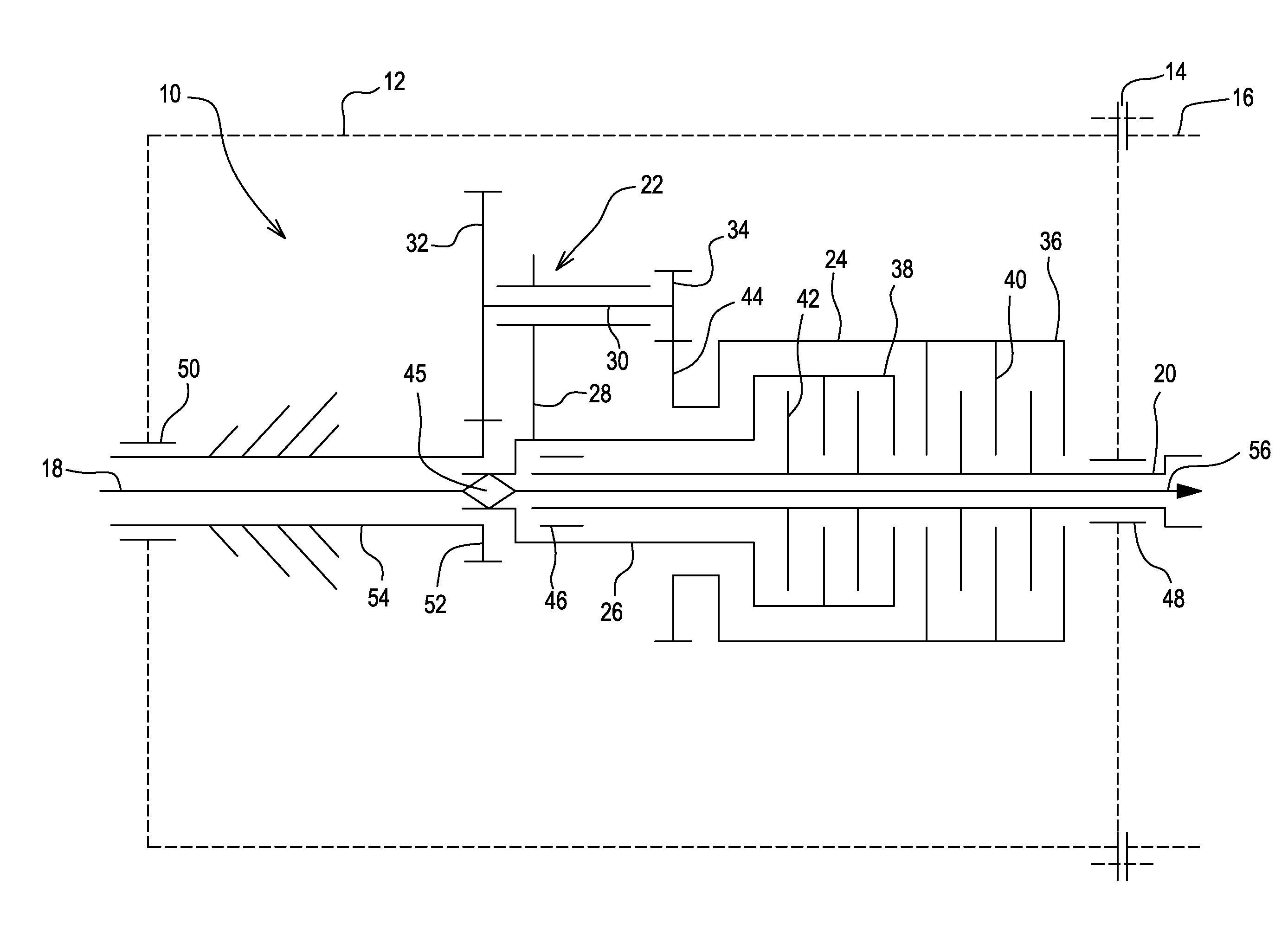
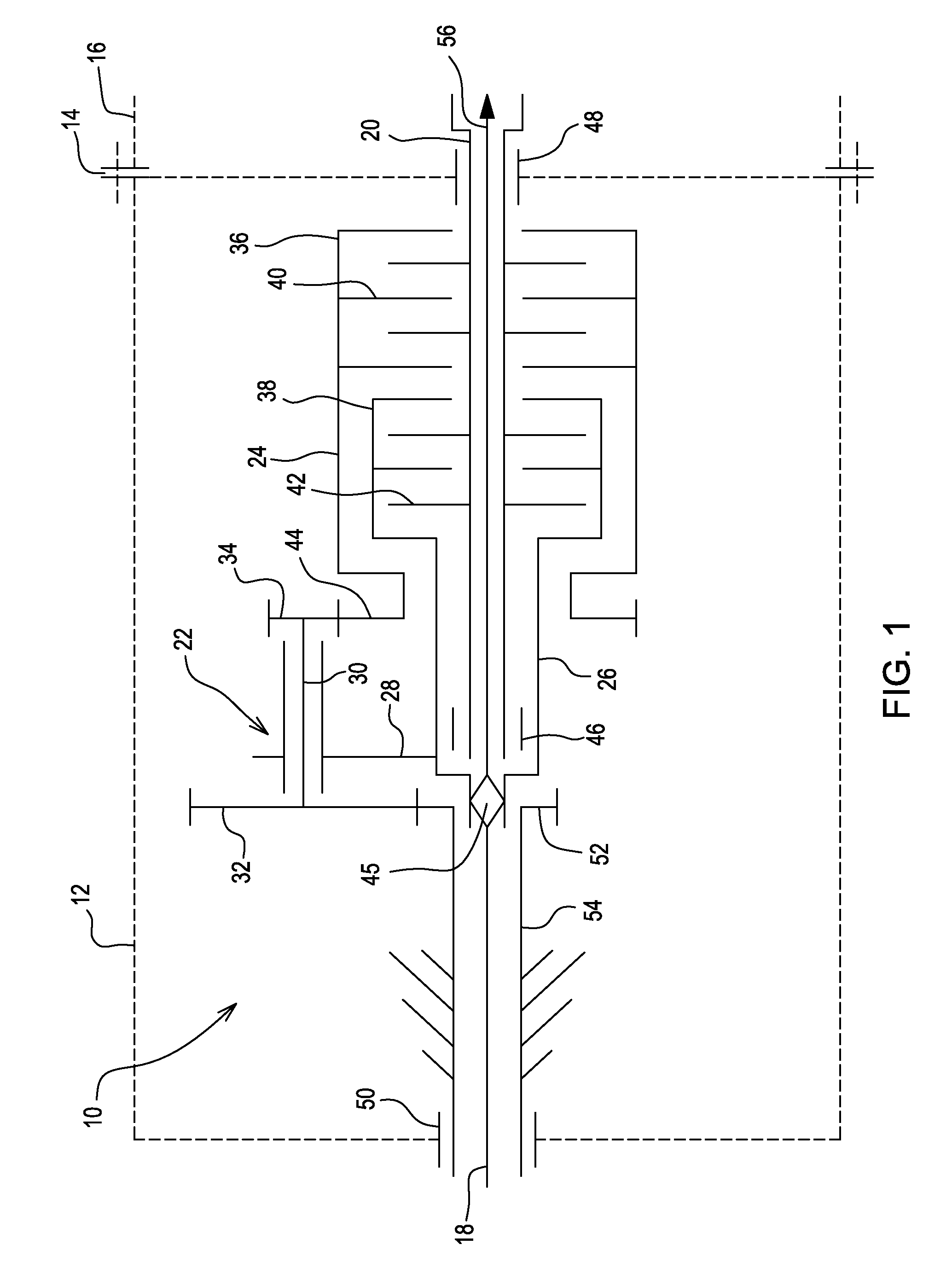
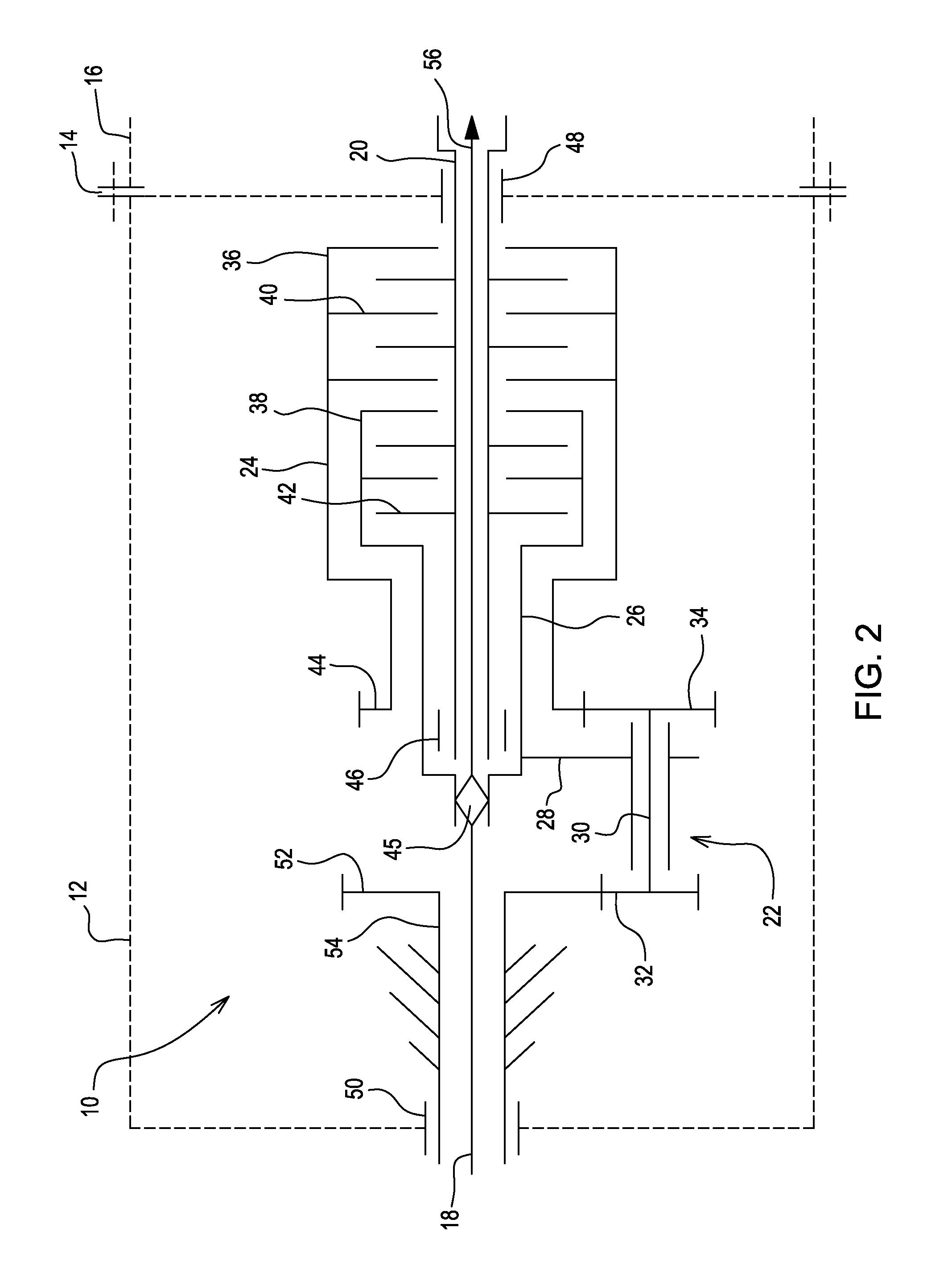
[0028]The power shift transmission 10 represented in FIG. 1 is designed as a variable modular transmission system and it includes a housing 12, which can be flange-mounted, for example, by means of a flange connection 14 to a main transmission housing 16, and which can be combined with a main transmission module (not shown) of an agricultural vehicle, for example, of a tractor or a tugboat.

[0029]The power shift transmission 10 comprises an input shaft 18 and a first output shaft 20, which can be brought into a drive connection by means of a planetary transmission 22 as well as by means of a first shift element 24 and a second shift element 26, which are both shown herein as clutches.

[0030]The planetary transmission 22 has a planet gear carrier 28, on which a dual-stage planetary gear set 30 is rotatably mounted. The dual-stage planetary gear set 30 comprises an input-side planet gear 32 as well as an output-side planet gear 34.

[0031]The first shift element 24 and the second shift el...


PUM


Abstract

The invention relates to a power shift transmission (10). The power shift transmission comprises an input shaft (18), a first output shaft (20) arranged coaxially to the input shaft (18), a planetary transmission (22) having a planet gear carrier (28), which is connected to the input shaft (18), and at least one dual-stage planetary gear set (30), the dual-stage planetary gear set (30) engaging on the input side with an input-side sun gear (52) and on the output side with an output-side sun gear (44) in each case, and at least two shift elements (24, 26). To produce a variable power shift transmission for several pairings of various operation modes, the first output shaft (20) can be connected to the output-side sun gear (44) of the dual-stage planetary gear set (30) by means of a first shift element (24) and the first output shaft (20) can be directly connected to the input shaft (18) by means of a second shift element (26), the input-side sun gear (52) of the dual-stage planetary gear set (30) being non-non-rotatably connected to a housing (12) of the power shift transmission (10).

Description

FIELD OF THE INVENTION[0001]The invention pertains to a power shift transmission comprising an input shaft, a first output shaft arranged coaxially to the input shaft, a planetary transmission having a planet carrier, which is connected to the input shaft, and at least one stepped planetary set, wherein the stepped planetary set engages on the input side and the output side with a sun gear, and at least two shift elements.BACKGROUND OF THE INVENTION[0002]Power shift transmissions having various transmission ratios, in which the shifting between the different transmission ratios occurs as a function of the load or of a required driving speed, are known and have been used for many years particularly in the automobile industry.[0003]Furthermore, it is known to design such transmissions in connection with planetary transmissions and clutches in a modular system, so that the power shift transmissions can be operated by an appropriate design and arrangement of the gear pairings of the pla...

Claims


Application Information

Patent Timeline
Patent Type & Authority Applications(United States)
IPC IPC(8): F16H3/46
CPCF16H3/46F16H2200/2035F16H2200/2007F16H2200/0034B60K17/28F16H3/56F16H2200/0004F16H2200/2005F16H2200/2097
Inventor OTTEN, ULRICHSCHALLER, MARTIN
Owner DEERE & CO
Why Eureka
Try Eureka