Electrode assembly manufacturing method including separator cutting process

a manufacturing method and separator technology, applied in the direction of cell components, final product manufacturing, sustainable manufacturing/processing, etc., can solve the problems of large thickness of separator sheets, large space utilization of devices, and large thickness of type electrode assemblies, so as to improve the productivity and yield rate of electrode assemblies having a different shape from a typical rectangular shape , the effect of efficient cutting a separator

Active Publication Date: 2015-02-05
LG ENERGY SOLUTION LTD
View PDF8 Cites 47 Cited by
  • Summary
  • Abstract
  • Description
  • Claims
  • Application Information

AI Technical Summary

Benefits of technology

[0014]According to the present invention, provided is an electrode assembly manufacturing method including a process of most efficiently cutting a separator to manufacture an electrode assembly having a shape different from a typical rectangular shape.
[0015]In addition, the separator is prevented from being damaged while the separator is cut.
[0016]In addition, the productivity and yield rate of electrode assemblies having a shape different from a typical rectangular shape are increased.

Problems solved by technology

However, the secondary batteries having a rectangular shape may confine the space utilization of the devices.
The jell-roll-type electrode assemblies are inappropriate for the chamfering and the forming of a through hole part.
Thus, the separator sheet has a significantly great thickness at an edge of the full cell and is thus significantly difficult to cut at a time.
However, in this case, it is difficult to accurately align layers of a stacked structure.
In addition, when a separator that is misaligned with an electrode is cut, the electrode may be damaged.
However, it is significantly inefficient to alternately stack the separators and electrodes after a cutting process, which significantly decreases productivity.
In addition, since the separators are soft and are easily deformed by heat, while the separators are stacked on the electrodes after the cutting process, the separators may become greater or smaller than a desired size.
Thus, it is difficult to manufacture an electrode assembly accurately having a desired size, and the yield rate of acceptable electrode assemblies is significantly decreased.

Method used


Image

  • Electrode assembly manufacturing method including separator cutting process
  • Electrode assembly manufacturing method including separator cutting process
  • Electrode assembly manufacturing method including separator cutting process

Examples


embodiment 1

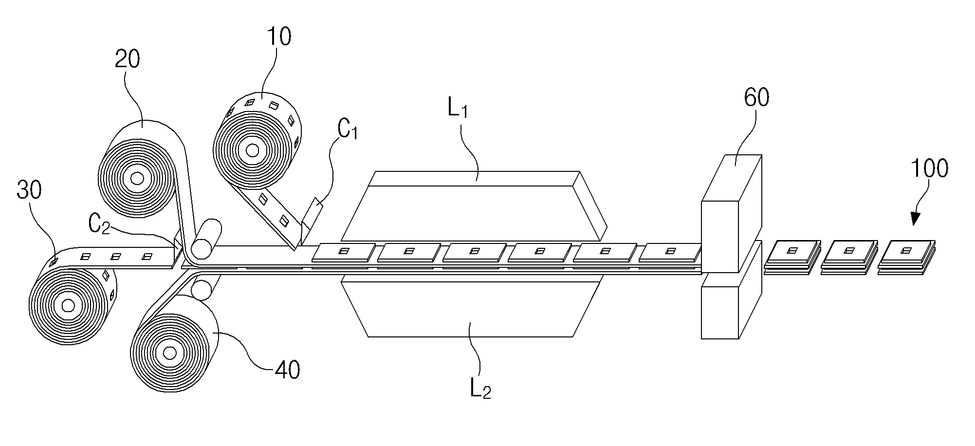
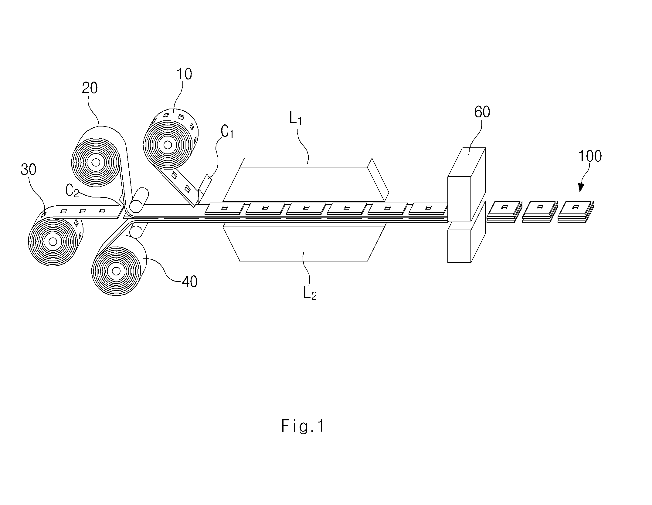
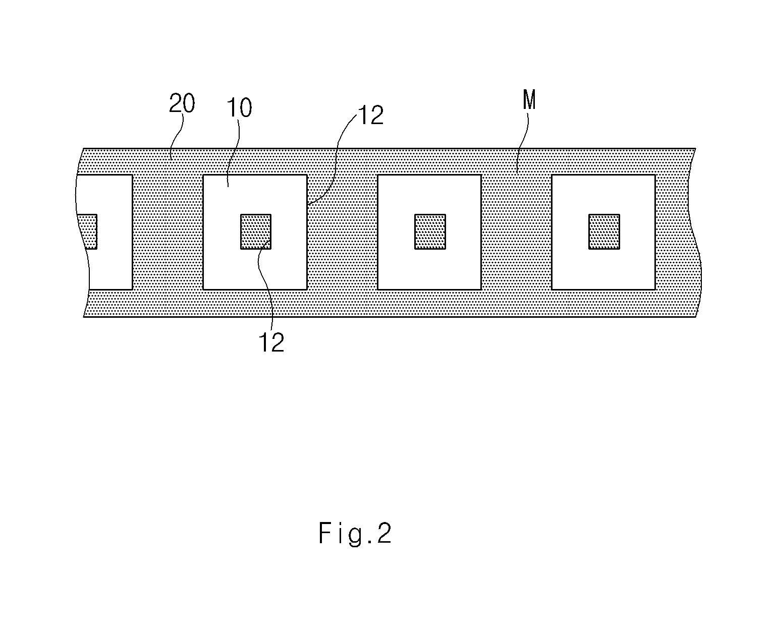
[0046]An electrode assembly manufacturing method according to a first embodiment of the present invention includes: a first process in which a first electrode material 10, a separator material 20, a second electrode material 30, and a separator material 40 sequentially undergo a laminating process to form a four-layer sheet; and a second-A process in which a portion of a margin area M of the separator materials 20 and 40, which are not covered with the first and second electrode materials 10 and 30, is cut using a mold cutter 60 such that the separator materials 20 and 40 of the four-layer sheet formed through the first process protrude over a specific distance D from edges 12 and 32 of the first and second electrode materials 10 and 30.

[0047][First Process]

[0048]The first process will now be described with reference to FIG. 1.

[0049]First, the first electrode material 10, the separator material 20, the second electrode material 30, and the separator material 40 are prepared. The sep...

embodiment 2

[0109]Hereinafter, an electrode assembly manufacturing method will now be described according to the second embodiment of the present invention. Here, different parts between the first and second embodiments will be described principally, and a description of the same parts thereof will be omitted.

[0110]Referring to FIG. 12, the electrode assembly manufacturing method according to the second embodiment includes: a first process in which a first electrode material 10, a separator material 20, a second electrode material 30, and a separator material 40 sequentially undergo a laminating process to form a four-layer sheet; a second-B process in which unit structures 100 formed by cutting the four-layer sheet formed through the first process, at regular intervals are stacked to form an electrode assembly; and a third process in which a portion of a margin area M is cut using a mold cutter 60 such that the separator materials 20 and 40 included in the electrode assembly formed through the...


PUM

PropertyMeasurementUnit
distanceaaaaaaaaaa
thicknessaaaaaaaaaa
thicknessaaaaaaaaaa

Abstract

Provided is an electrode assembly manufacturing method including a process of cutting a separator included in an electrode assembly to have a margin protruding from an electrode plate. The method includes a first process of manufacturing one type of basic unit sheets having a structure in which electrode materials and separator materials, which are the same in number, are alternately stacked, or two or more types of basic unit sheets having a structure in which electrode materials and separator materials, which are the same in number, are alternately stacked, and a second-A process of cutting a portion of a margin area of the separator materials, which are not covered with the electrode materials, such that the separator materials of the basic unit sheets protrude over a specific distance from edges of the electrode materials.

Description

CROSS-REFERENCE TO RELATED APPLICATIONS[0001]This application claims the priority of Korean Patent Application No. 10-2013-0075189 filed on Jun. 28, 2013, and Application No. 10-2014-0079517 filed on. Jun. 27, 2014 in the Korean Intellectual Property Office, the disclosures of which are incorporated herein by reference.FIELD OF THE INVENTION[0002]The present invention relates to an electrode assembly manufacturing method including a separator cutting process, and more particularly, to an electrode assembly manufacturing method including a process of cutting a separator included in an electrode assembly to have a margin protruding from an electrode plate.DISCUSSION OF RELATED ART[0003]As mobile devices are technically developed and are in increasing demand, demands for secondary batteries quickly increase. Of these secondary batteries, lithium (ion / polymer) secondary batteries which have high energy density, high operation voltage, and excellent preservation and service life characte...

Claims


Application Information

Patent Timeline
Patent Type & Authority Applications(United States)
IPC IPC(8): H01M10/058H01M4/04H01M50/451
CPCH01M4/0402H01M10/058H01M10/0463H01M10/0585H01M10/052H01M10/0404H01M50/461H01M50/446H01M50/451Y10T29/49108Y10T29/49114Y10T29/49115Y02E60/10Y02P70/50H01M10/0436H01M10/0413
Inventor YANG, YOUNG JOOAN, KYOUNG JINSUL, DONG HEE
Owner LG ENERGY SOLUTION LTD
Why Eureka
Try Eureka