Electrically controlled silicon oil fan clutch rotary valve device

a technology of silicon oil fan and clutch, which is applied in the direction of clutches, mechanical equipment, machines/engines, etc., can solve the problems of constant valve jitter, unstable flow velocity of silicon oil, and affecting the rotation speed of the fan, so as to achieve stably and effectively control the effect of the intermediate speed and controllable speed

Active Publication Date: 2015-02-05
SUZHOU RISING AUTO PARTS
View PDF3 Cites 15 Cited by
  • Summary
  • Abstract
  • Description
  • Claims
  • Application Information

AI Technical Summary

Benefits of technology

[0007]Objective: an objective of the present invention is to provide an electrically controlled silicon oil fan clutch rotary valve device which is under high-precision control, responds quickly, is slightly affected by silicon oil, and may achieve stepless speed regulation of the fan.
[0012]The guide disc includes an annular body, a convex ring disposed on a periphery of the body and internally connected to the driven disc, and a concave ring corresponding to the driving disc. The convex ring achieves a tight connection between the driven disc and the guide disc, and the design of the concave ring renders a gap formed between the driving disc and the guide disc for feeding of the silicon oil.
[0013]Beneficial effect: the electrically controlled silicon oil fan clutch rotary valve device in the present invention uses a rotary valve structure, capable of controlling the valve to be stable at an appropriate position through the size of current of a coil, so that intermediate speeds are stably and effectively controlled; the greater the current passed to the coil is, the larger the rotation angle of the driving disc is, so that the torsion spring automatically resets. The present invention could stably control the fan at any speed between low speeds and high speeds through an automobile ECU, so as to achieve a stepless speed and achieve a purpose of precisely controlling the clutch.

Problems solved by technology

A current electrically controlled clutch adopts valve opening and closing, which is relatively stable only at the high speed and the low speed, and is unstable at an intermediate process speed, moreover, a moving direction of a valve is perpendicular to a direction of flow velocity, the silicon oil may push the valve during the flow, resulting in that the valve jitters endlessly, and the jitter may cause the flow velocity of the silicon oil to be unstable, thereby affecting the rotation speed of the fan.
Therefore, if the existing valve intends to achieve precise control, it still has a long way to go.
An existing clutch mostly uses a spiral bimetallic temperature sensor or a sheet-like bimetallic temperature sensor, and its defects include: 1. temperature sensing sensitivity is not high, the reaction is slow, and the engine cooling problem may not be solved efficiently; 2. control precision is low, and it is not the ideal linear element; 3. it is easy to be affected by external temperatures and distance between the clutch and a radiator; 4. temperature adjustment and control only can be performed through the radiator, and control elements are single; 5. as the degree of deformation of the temperature sensor is limited, the control over the temperature is limited; 6. actions are taken only based on temperature change of the radiator, and the control is relatively passive; and 7. only open-loop control can be achieved.

Method used


Image

  • Electrically controlled silicon oil fan clutch rotary valve device
  • Electrically controlled silicon oil fan clutch rotary valve device
  • Electrically controlled silicon oil fan clutch rotary valve device

Examples


Embodiment Construction

[0023]The present invention is further described in the following in combination with specific embodiments.

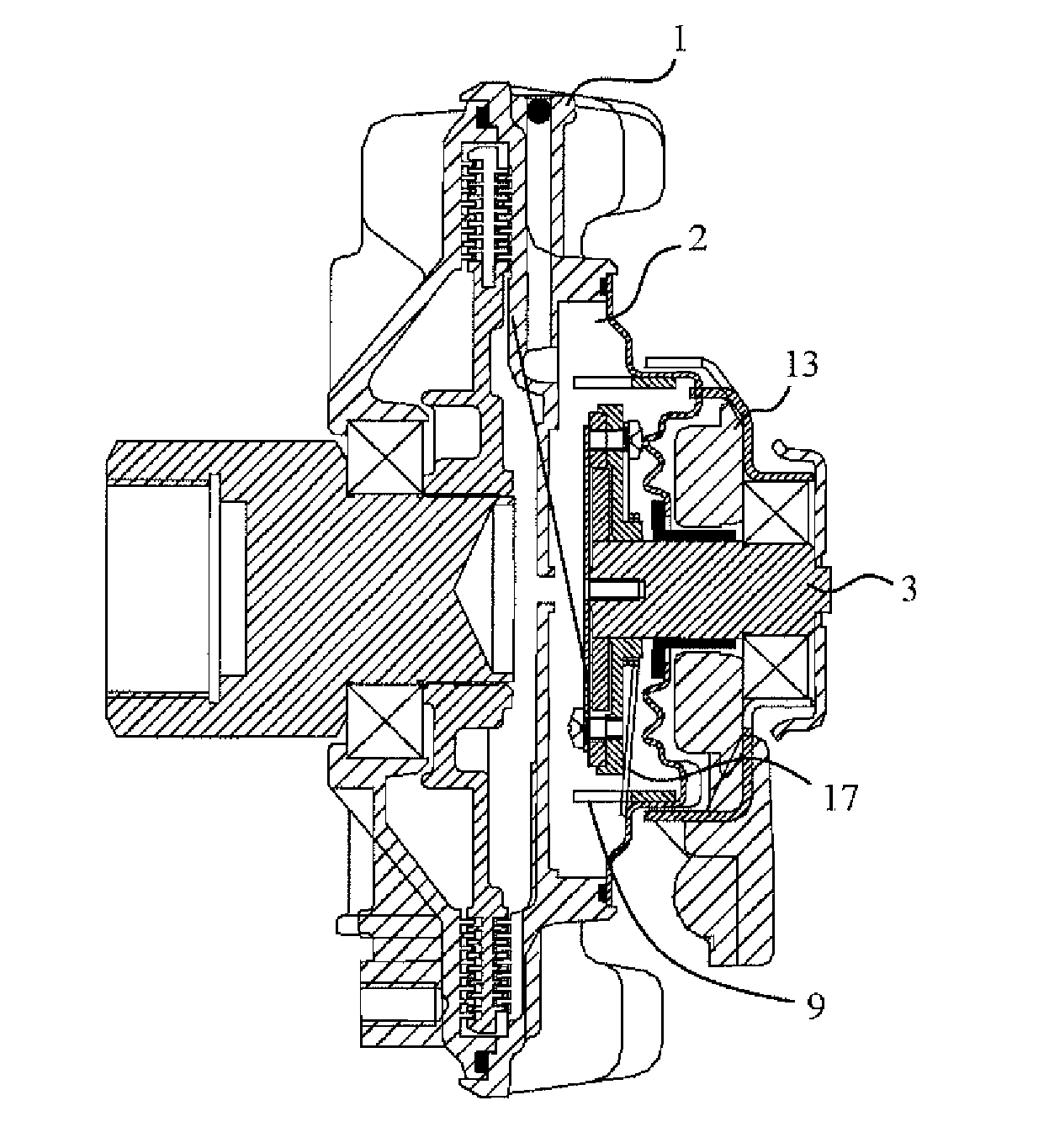
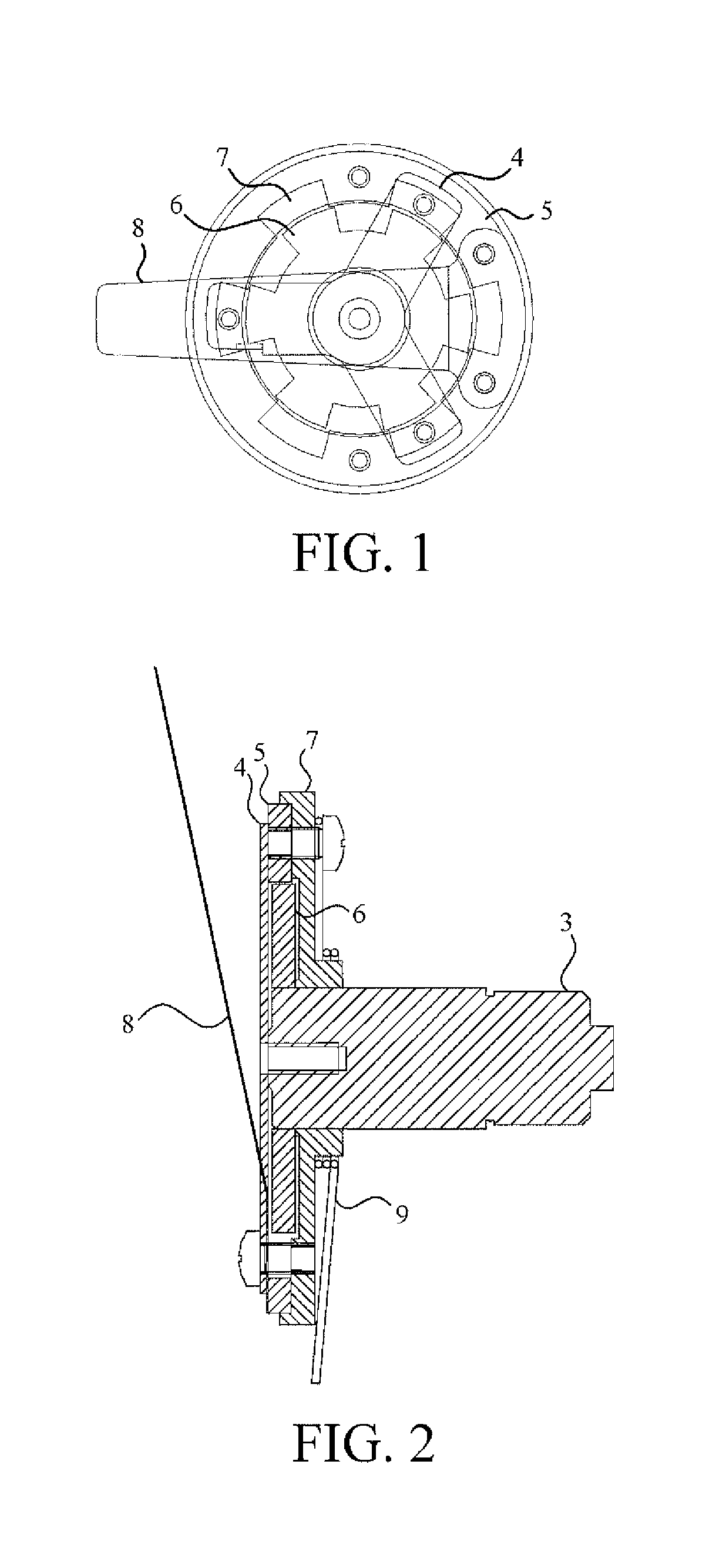
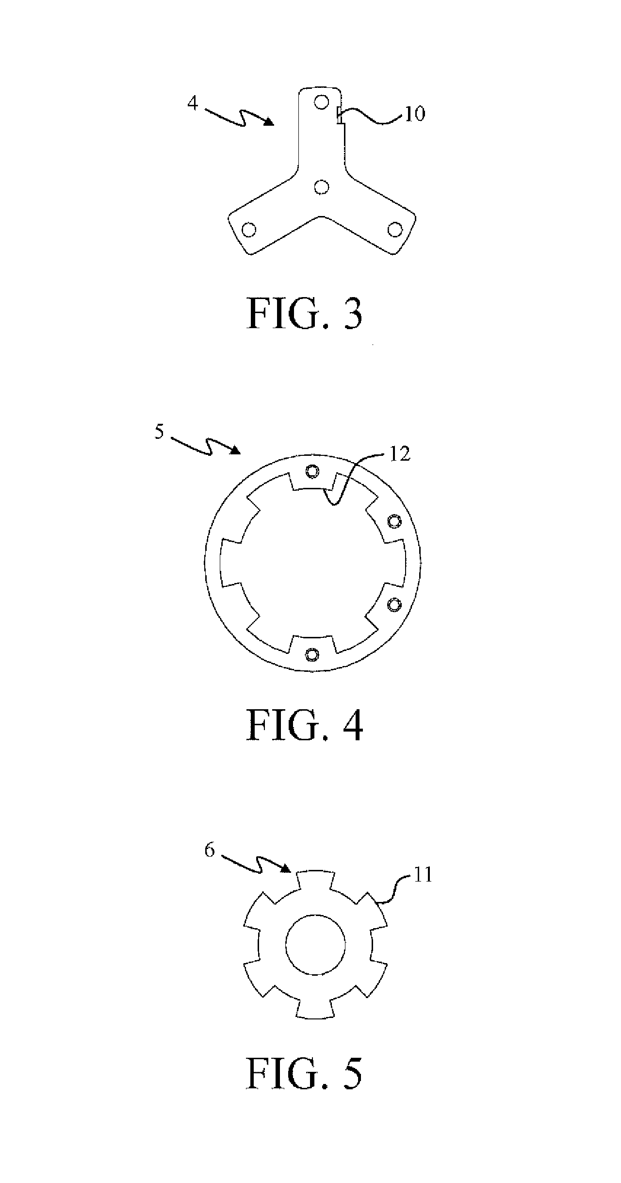
[0024]Referring to FIG. 1 to FIG. 9, an electrically controlled silicon oil fan clutch rotary valve device according to the present invention is disposed at one side of an oil storage cavity 2 of a silicon oil fan clutch end-cover 1, including a magnetic mandrel 3, where the magnetic mandrel 3 is provided with an electromagnetic coil 13 of an input duty cycle voltage signal externally. The electromagnetic coil 13 is energized to generate a magnetic field, and magnetic energy is guided into the driving disc 6 through a mandrel 3 magnet, so as to make it rotate. The valve device includes a triangle 4 with an opening cut in the center, a driven disc 5, a driving disc 6, a guide disc 7, a valve 8, and a torsion spring 9; the magnetic mandrel 3 passes through the guide disc 7 and the driving disc 6 sequentially, and is connected to the triangle 4 in a front end of the magnetic mandr...


PUM


Abstract

Disclosed is an electrically controlled silicon oil fan clutch rotary valve device. The valve device is based on a magnetic mandrel, including a triangle, a driven disc, a driving disc, and a guide disc intercombined, which achieves control over flow of silicon oil by controlling rotation of a valve, and achieves precise control over positions by resetting through a reset torsion spring and using outer teeth and inner teeth of the driving disc and the driven disc as well as a stop device. In the present invention, the valve may be controlled to be stable at an appropriate position through the size of the current of the coil, so as to achieve a stepless speed and achieve a purpose of precisely controlling the clutch.

Description

BACKGROUND OF THE INVENTION[0001]1. Field of the Invention[0002]The present invention relates to the field of automobile parts, and specifically to an electrically controlled silicon oil fan clutch rotary valve device.[0003]2. Related Art[0004]Automobile energy saving is a long-term policy of national economic development, energy consumption of the automobile fan accounts for 5%-10% of energy of the engine, and in fact, automobiles require fan cooling only in about 10% of the time. So, automobile fan energy saving is a key technology of the automobile energy saving.[0005]An existing automobile silicon oil fan clutch uses a temperature sensor technology, and its working principle is transforming a thermal load condition of the engine into a rotation motion through a bimetallic temperature sensor, and opening a valve hole, so that silicon oil enters a working cavity to drive a fan to move at a high speed; when a load of the engine is low, the temperature sensor drives the valve to clo...

Claims


Application Information

Patent Timeline
Patent Type & Authority Applications(United States)
IPC IPC(8): F16D48/02
CPCF16D25/14F16D35/024F01P7/042F01P7/084
Inventor YUE, SHENGQIAOGONG, DAJIN
Owner SUZHOU RISING AUTO PARTS
Why Eureka
Try Eureka