Permanent magnet inductor filter apparatus and method of use thereof

a permanent magnet inductor and filtering technology, which is applied in the direction of dynamo-electric converter control, motor/generator/converter stopper, energy industry, etc., can solve the problems of overheating of the cables and any associated devices, such as motors, and severe increase in ac resistance of cables

Inactive Publication Date: 2015-02-05
CTM MAGNETICS
View PDF6 Cites 19 Cited by
  • Summary
  • Abstract
  • Description
  • Claims
  • Application Information

AI Technical Summary

Problems solved by technology

When frequencies in the 50-100 kHz range are added to the current spectrum, the industrial power cables overheat because of the high frequency travels only on the outside diameter of the conductor causing a severe increase in AC resistance of the cable and resultant overheating of the cables and any associated device, such as a motor.

Method used


Image

  • Permanent magnet inductor filter apparatus and method of use thereof
  • Permanent magnet inductor filter apparatus and method of use thereof
  • Permanent magnet inductor filter apparatus and method of use thereof

Examples


Embodiment Construction

[0042]The invention comprises an inductor filter apparatus and method of use thereof.

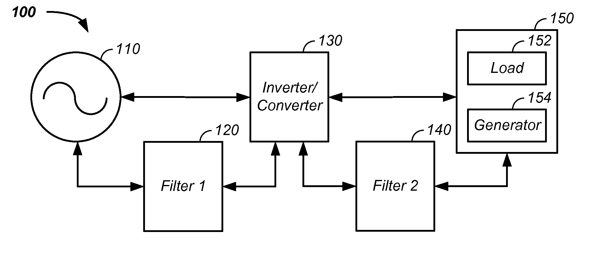
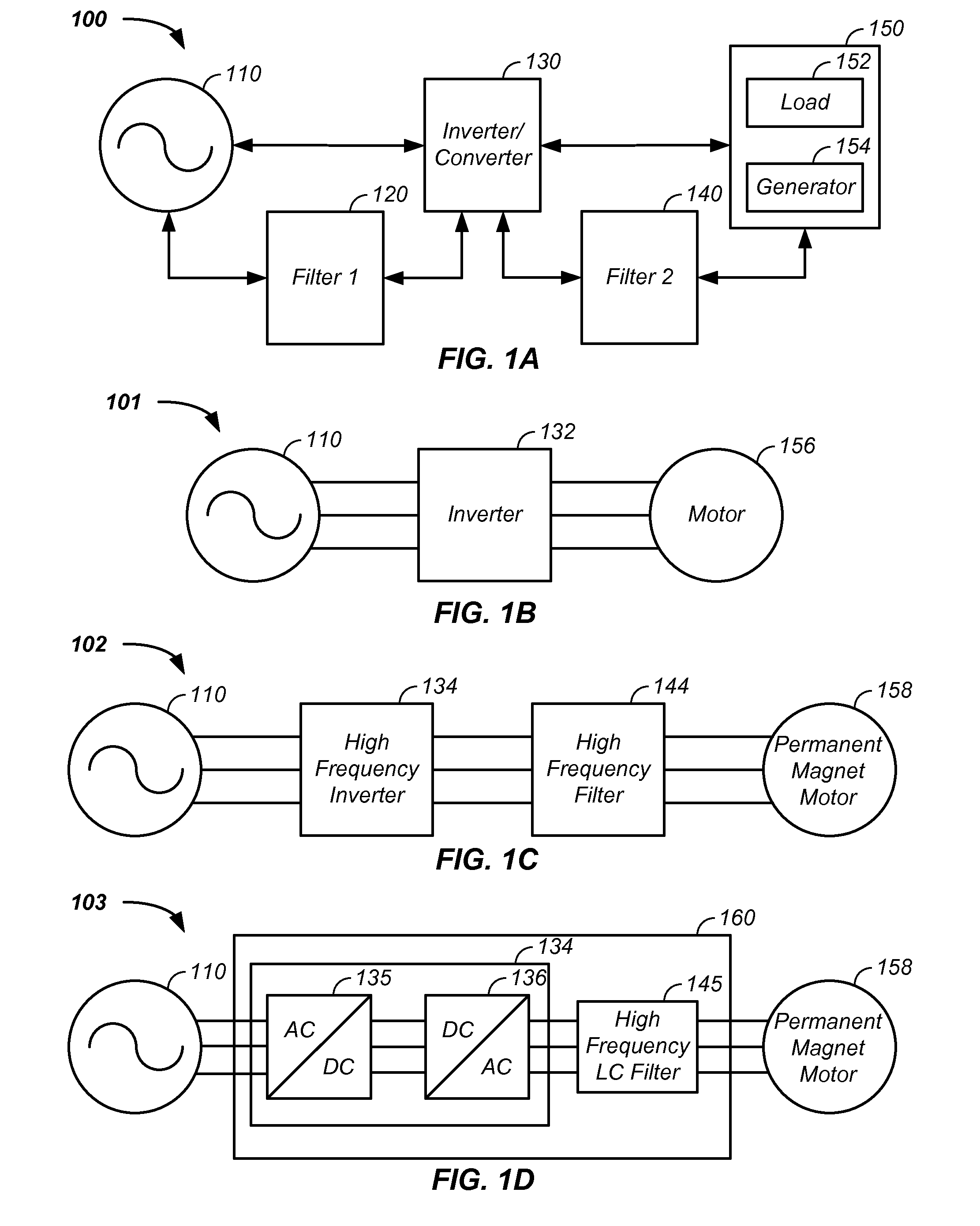
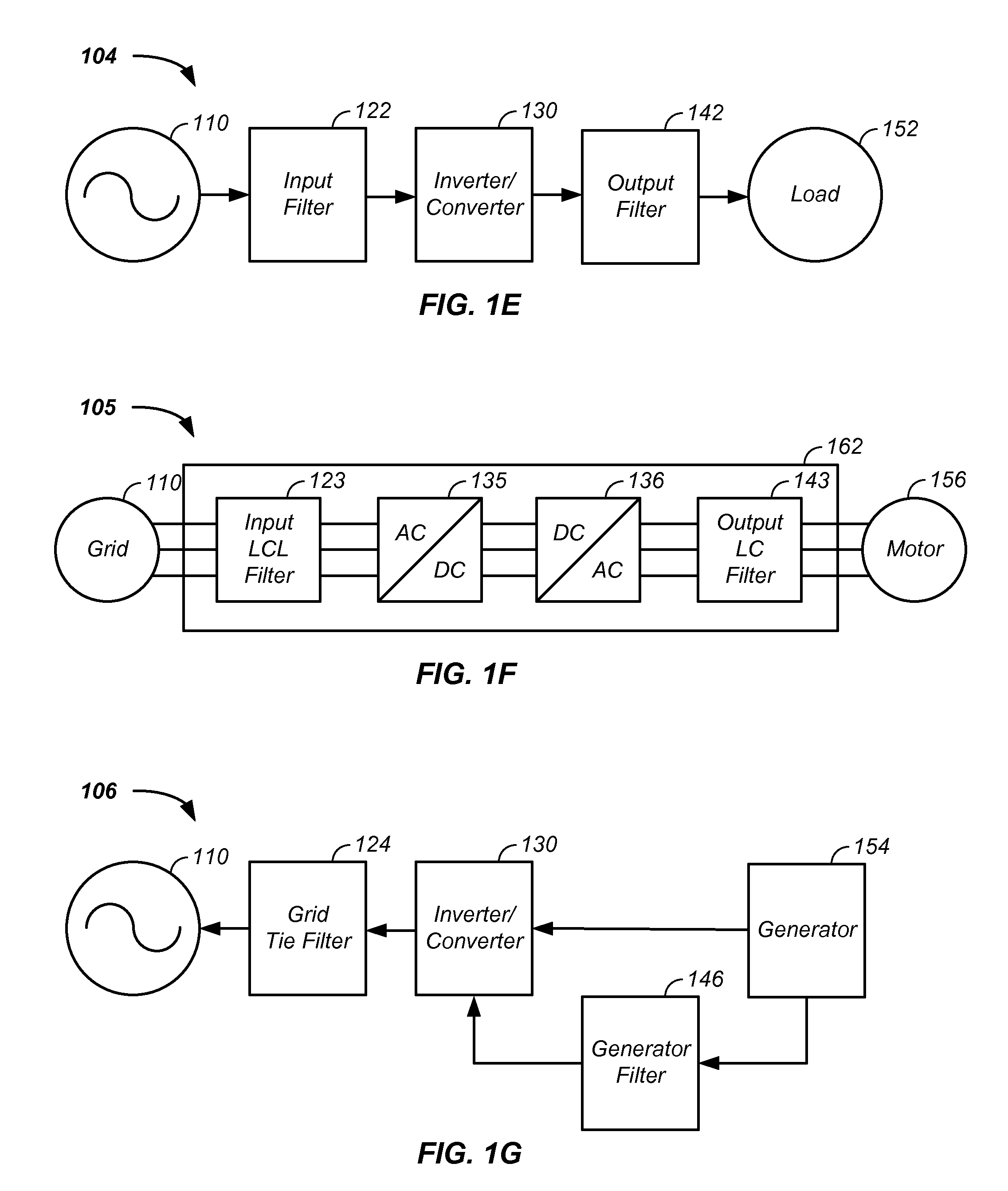
[0043]In one embodiment, an inverter and / or an inverter converter system yielding high frequency harmonics, referred to herein as a high frequency inverter, is coupled with a high frequency filter to yield clean power, reduced high frequency harmonics, and / or an enhanced energy processing efficiency system. In one case, a silicon carbide insulated gate bipolar transistors (IGBT) is used in the conversion of power from the grid and the IGBT outputs current, voltage, energy, and / or high frequency harmonics greater than 60 Hz to an output filter, such as a distributed gap inductor, which filters the output of the IGBT. In one illustrative example, a high frequency inductor and / or converter apparatus is coupled with a high frequency filter system, such as an inductor linked to a capacitor, to yield non-sixty Hertz output. In another illustrative example, an inductor / converter apparatus using a silicon c...


PUM


Abstract

The invention comprises a high frequency inductor filter apparatus coupled with an inverter yielding high frequency harmonics and / or non-sixty Hertz output. For example, an inductor / converter apparatus is provided that uses a silicon carbide transistor to output power having a carrier frequency, modulated by a fundamental frequency, and a set of harmonic frequencies. A filter, comprising an inductor having a distributed gap core material and optional magnet wires, receives power output from the inverter / converter and processes the power by passing the fundamental frequency while reducing amplitude of the harmonic frequencies.

Description

CROSS REFERENCES TO RELATED APPLICATIONS[0001]This application:[0002]is a continuation-in-part of U.S. patent application Ser. No. 13 / 470,281 filed May 12, 2012, which is a continuation-in-part of U.S. patent application Ser. No. 13 / 107,828 filed May 13, 2011, which[0003]is a continuation-in-part of U.S. patent application Ser. No. 12 / 098,880 filed Apr. 4, 2008, which[0004]claims benefit of U.S. provisional patent application No. 60 / 910,333 filed Apr. 5, 2007; and[0005]is a continuation-in-part of U.S. patent application Ser. No. 11 / 156,080 filed Jun. 15, 2005 (now U.S. Pat. No. 7,471,181), which claims benefit of U.S. provisional patent application No. 60 / 580,922 filed Jun. 17, 2004;[0006]is a continuation-in-part of U.S. patent application Ser. No. 12 / 197,034 filed Aug. 22, 2008, which claims benefit of U.S. provisional patent application No. 60 / 957,371, filed on Aug. 22, 2007; and[0007]is a continuation-in-part of U.S. patent application Ser. No. 12 / 434,894 filed Aug. 2, 2010, wh...

Claims


Application Information

Patent Timeline
Patent Type & Authority Applications(United States)
IPC IPC(8): H02M1/12
CPCH02M1/12H01F27/085H01F27/255H01F27/266H01F27/2895H01F27/306H02M1/126H02M5/458H02M7/5387Y02B70/10Y02P80/20
Inventor MACLENNAN, GRANT A.
Owner CTM MAGNETICS
Why Eureka
Try Eureka