Micromirror

a micro-mirror and mirror technology, applied in the field of micro-mirrors, can solve the problems of temperature-dependent static deformation of the mirror, poor image resolution, and difficult to meet requirements, and achieve the effect of flat structural shap

Active Publication Date: 2015-02-05
ROBERT BOSCH GMBH
View PDF5 Cites 9 Cited by
  • Summary
  • Abstract
  • Description
  • Claims
  • Application Information

AI Technical Summary

Benefits of technology

[0013]The tilt angle of the mirror plate should be as large as possible, but at least 10°. This requires a specific spring length, so that the stress in the spring does not become excessively large. It is known from the classical case of a flexible spring that with increasing curvature and increasing distance of the surface from the neutral fiber, the stress on the surface of the spring increases. If a large bending angle and a high stiffness are required, the stress in the spring may only be decreased by a greater spring length l. A long spring having a large cross section is thus necessary to implement a stiff spring, which does not break in the event of a large deflection. Simultaneously, the chip surface should be as small as possible, since the costs increase proportionally in this way.
[0025]One advantageous embodiment of the micromirror according to the present invention provides that a first frame is implemented in the first layer and the spring element is connected to the first frame. The spring element may advantageously be suspended in the first layer in this way, and the micromirror thus obtains a particularly flat structural shape. One particularly advantageous embodiment of the micromirror according to the present invention provides that a second frame is implemented in the second layer, which is connected to the first frame via the connection area. The frame may advantageously be reinforced in this way.

Problems solved by technology

In the event of a greater deformation, the spot would be widened, which worsens the resolution of the image.
Because of the inertia of the mirror itself and the counterforces acting on the mirror plate, as are exerted by the springs tensioned upon deflection of the mirror, this is a requirement which is very difficult to meet.
This results in temperature-dependent static deformation of the mirror.

Method used


Image

  • Micromirror
  • Micromirror
  • Micromirror

Examples


Embodiment Construction

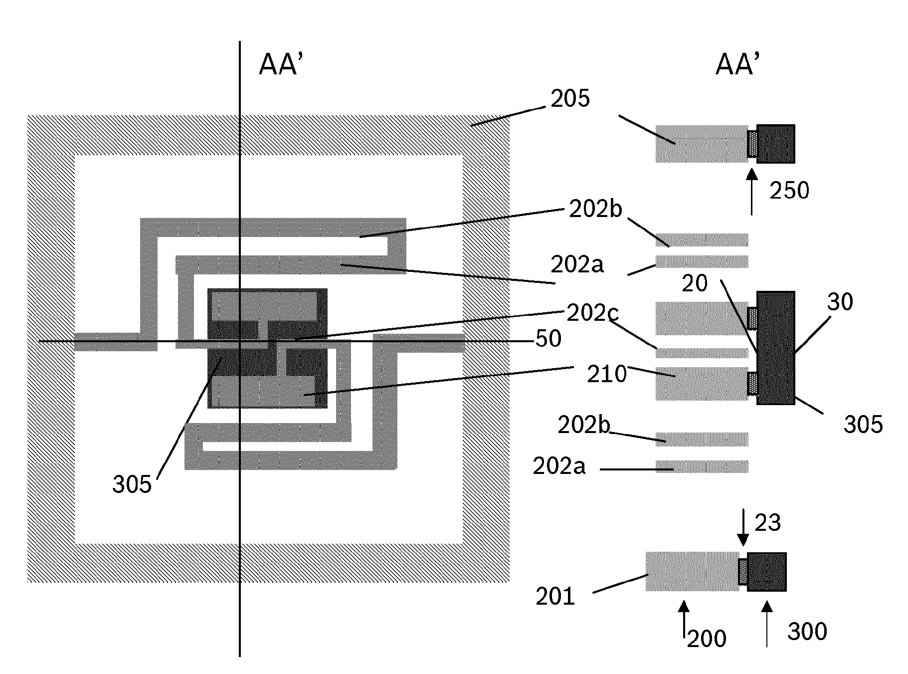
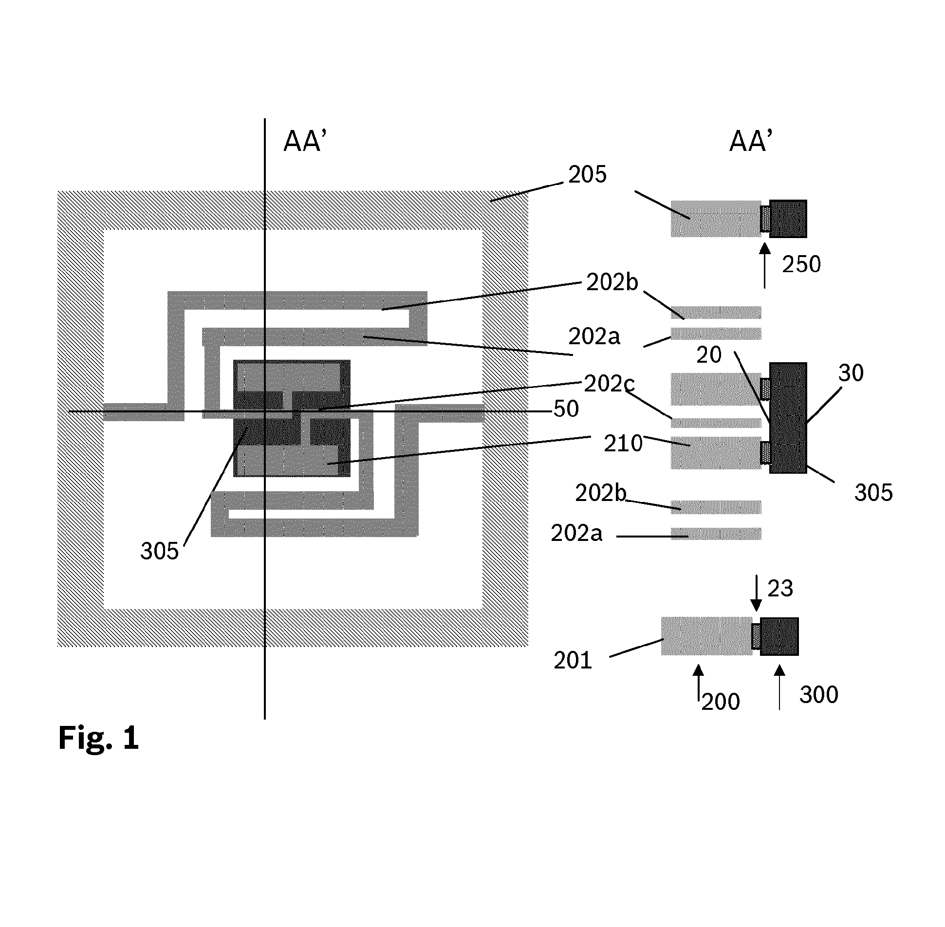
[0034]FIG. 1 shows a first exemplary embodiment of the micromirror according to the present invention. A micromirror is shown including a first layer 200 having a first main extension plane, a second layer 300 having a second main extension plane, the first main extension plane and the second main extension plane being situated parallel to one another, and first layer 200 and second layer 300 being sectionally connected to one another via at least one connection area 23. At least one spring element, in this example two spring elements 202, are implemented in first layer 200. A movably suspended mirror plate 305 is implemented in second layer 300, mirror plate 305 having a mirror surface on a first side 30 parallel to the main extension plane and being connected on an opposing second side 20 via connection area 23 to an anchor 210 of spring element 202. A part of spring element 202 is, spaced apart by connection area 23, movably situated on second side 20 of mirror plate 305 in relat...


PUM


Abstract

A micromirror including a first layer having a first main extension plane, and a second layer having a second main extension plane, the first main extension plane and the second main extension plane being situated parallel to one another, the first layer and the second layer being sectionally connected to one another via at least one connection area, at least one spring element being implemented in the first layer, a movably suspended mirror plate being implemented in the second layer, the mirror plate having a mirror surface on a first side parallel to the main extension plane and being connected on an opposing second side via the connection area to an anchor of the spring element, a part of the spring element on the second side of the mirror plate being movably situated in relation to the mirror plate. A two-mirror system having such a micromirror is also provided.

Description

BACKGROUND INFORMATION[0001]A movement at high frequency in at least one axis is necessary to build up an image with the aid of line-by-line writing of a projection area (“flying spot”). Exclusively resonant oscillating arrangements come into consideration to achieve the required frequencies greater than 10 kHz up to 50 kHz. A great variety of micromirrors have been provided in recent years. In part, mirrors have been implemented which oscillate only in one axis; in part, gimbal-mounted mirrors have been developed, which either perform resonant oscillations in both axial directions, or operate quasi-statically in one direction.[0002]The significance of the product of mirror size and deflection, the so-called theta-D product, and the frequency for the image quality of a microscanner are described in MEMS Scanners for Display and Imaging Applications, Proc. of SPIE, volume 5604.[0003]In addition to the three parameters mirror size, deflection, and frequency, the mirror deformation of ...

Claims


Application Information

Patent Timeline
Patent Type & Authority Applications(United States)
IPC IPC(8): G02B26/08G02B26/10
CPCG02B26/101G02B26/0833G02B7/1821G02B26/105B81B2203/0163B81B3/0043B81B2201/042B81B2203/0109
Inventor NITSCHE, HEIKONJIKAM NJIMONZIE, FREDERICSCHOCK, WOLFRAMMUCHOW, JOERGGRUTZECK, HELMUTLESTYAN, ZOLTAN
Owner ROBERT BOSCH GMBH
Why Eureka
Try Eureka