Methods and preforms to mask holes and support open-substrate cavities during laser cladding

a technology of laser cladding and masking holes, which is applied in the direction of manufacturing tools, machines/engines, turbines, etc., can solve the problems of compromising the mechanical integrity of the alloy substrate and the cladding layer, unable to maintain the cooling hole free of obstructions and within the design limits of size and shape, and the superalloy materials are among the most difficult to fabricate and repair

Inactive Publication Date: 2015-02-05
SIEMENS ENERGY INC
View PDF6 Cites 61 Cited by
  • Summary
  • Abstract
  • Description
  • Claims
  • Application Information

AI Technical Summary

Problems solved by technology

However, maintaining the cooling holes free of obstructions and within design limits of size and shape is especially difficult when performing repairs of components fabricated using superalloy materials, which are often employed in modern gas turbine components subject to increasingly higher temperatures.
Superalloy materials are among the most difficult to fabricate and repair due to their susceptibility of melt solidification cracking and strain age cracking.
Performing these techniques over holes or cavities present on an outer surface of the alloy substrate, however, can jeopardize the mechanical integrity of both the alloy substrate and the cladding layer.
Furthermore, because the hole imparts a thermal discontinuity during the laser melting process, over-penetration (i.e., excess melting) can lead to cracking 22 in the superalloy substrate

Method used


Image

  • Methods and preforms to mask holes and support open-substrate cavities during laser cladding
  • Methods and preforms to mask holes and support open-substrate cavities during laser cladding
  • Methods and preforms to mask holes and support open-substrate cavities during laser cladding

Examples


Embodiment Construction

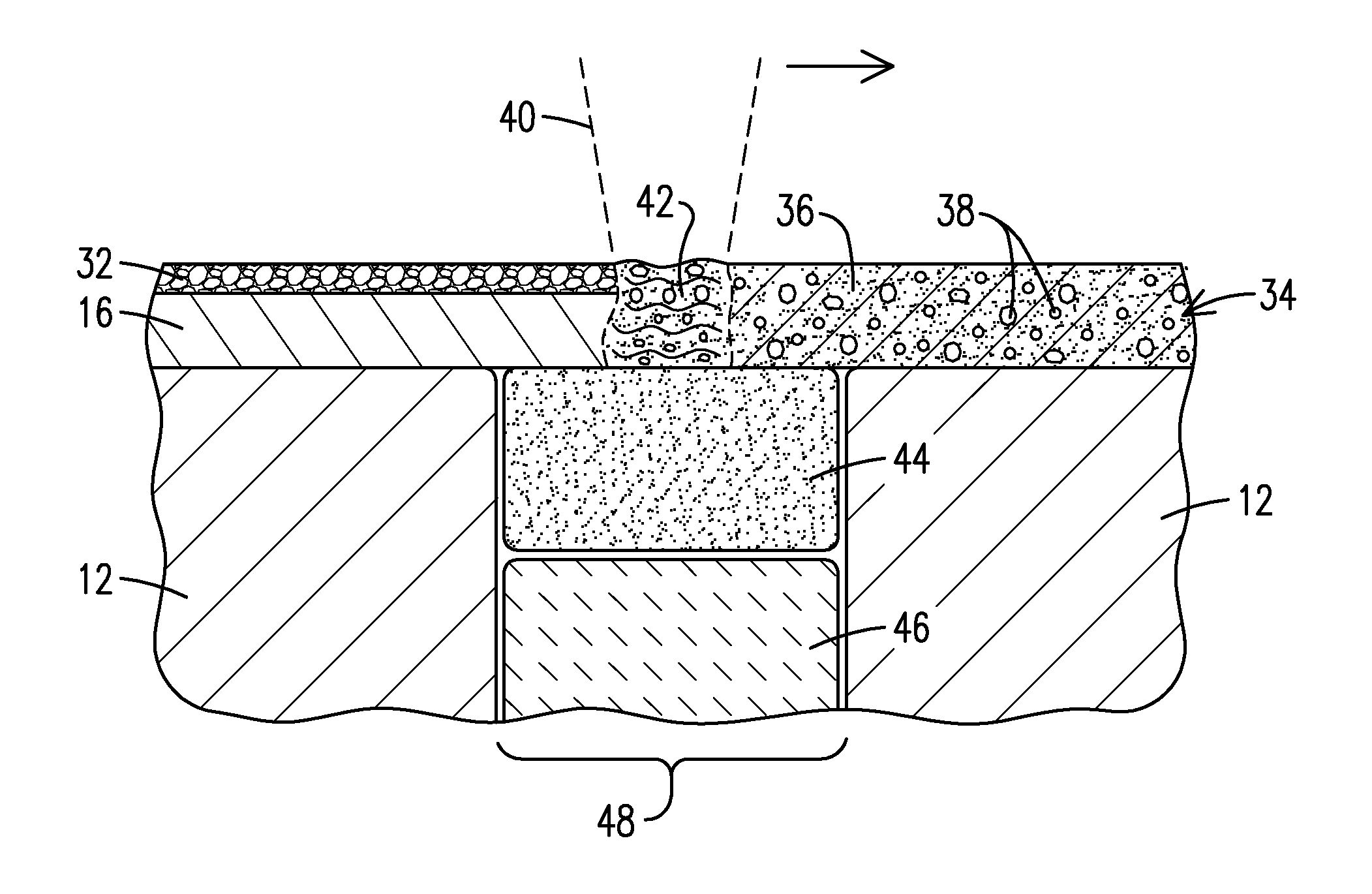
[0019]The present inventors have discovered novel methods and materials for forming metallic cladding layers over open cavities and holes located in metallic components. In these disclosures, a protective material is employed which can function as a supportive structure (reducing or preventing a molten metal from entering the open space), a barrier structure (preventing a molten metal from entering the open space and optionally defining the shape of the resulting cladding layer), and as a protective agent (reducing or preventing chemical and / or mechanical imperfections in the resulting cladding layer). Such protective support or blocking materials may exist as individual (standalone) structures, or beds of material, or as multi-layered preform structures constructed of metallic filler-containing compartments and at least one protective supporting compartment. The use of multi-layered preform structures enables the additive manufacture and repair of relatively large, hollow superallo...


PUM

PropertyMeasurementUnit
Metallic bondaaaaaaaaaa

Abstract

This invention relates to methods in which a protective material (44) is introduced into a metallic component, or is used to block a hole (48) in the metallic component, a filler material (34) is pre-placed or directed to an external surface of the metallic component, the filler material is heated with at least one energy beam (40) to melt or sinter a metal powder (36) contained in the filler material to form a cladding layer (16), and the protective material is removed from the metallic component, such that the protective material contains, or generates upon being heated, a protective substance. The present invention also relates to preforms (72) containing an upper section (74) containing a powdered metal (36) and a flux (38), and a lower section (76) containing a protective material (78), such that the protective material contains, or generates upon being heated, a protective substance.

Description

[0001]This application is a continuation-in-part of U.S. patent application Ser. No. 13 / 956,635 filed on 1 Aug. 2013 (attorney docket number 2013P12505US), incorporated herein by reference.FIELD OF THE INVENTION[0002]This invention relates generally to the field of metal-component fabrication and repair, and more particularly to the fabrication and repair of hollow superalloy components containing cavities and / or holes.BACKGROUND OF THE INVENTION[0003]Modern gas turbines require cooling systems to protect the turbine blades, vanes, endwalls, shroud and other components from the increasingly higher metal temperatures that are demanded for improved performance. There are five basic cooling techniques employed in modern gas turbine engines: convection cooling, impingement cooling, film cooling, transpiration cooling and water / steam cooling. Several of these techniques rely in part on the placement of holes or cavities in vital engine components to facilitate fluid flow.[0004]FIG. 1 ill...

Claims


Application Information

Patent Timeline
IPC IPC(8): B05D3/02
CPCB05D3/0254B05D2401/40B05D2202/00B23P6/007F01D5/005B22F2005/103B22F2007/068B23P2700/06F01D5/186F01D5/288F05D2230/22B23K26/34B23K26/706B23K2101/001B23K2103/26Y10T428/31678Y02P10/25B22F10/43B22F10/28B22F10/25B22F10/47
Inventor BRUCK, GERALD J.KAMEL, AHMED
Owner SIEMENS ENERGY INC
Why Eureka
Try Eureka