Heat conduction device included crucible

a heat conduction device and crucible technology, applied in lighting and heating apparatus, furnace types, furnaces, etc., can solve the problems of not being able to transfer heat, the method is only effective for sublimation type materials, and the material decomposition on the top side is possibl

Inactive Publication Date: 2015-02-05
TCL CHINA STAR OPTOELECTRONICS TECH CO LTD
View PDF3 Cites 1 Cited by
  • Summary
  • Abstract
  • Description
  • Claims
  • Application Information

AI Technical Summary

Benefits of technology

[0013]An object of the present invention is to provide a heat conduction device included crucible, which has an excellent effect of heat conduction and can stably vaporize an organic material, reduce the potential risk of decomposition of the organic material, so as to improve the effectiveness of vapor deposition.
[0031]The efficacy of the present invention is that the present invention provides a heat conduction device included crucible, which is used in a coater for vapor deposition of an organic material of an organic light-emitting diode, wherein through an arrangement of a tree-like heat conduction device in the crucible body to transfer heat in every direction within the crucible body so that during a vapor deposition operation, an organic material received in the crucible body can be heated uniformly thereby avoiding the phenomenon of partial decomposition of the organic material occurring in the prior art technique due to non-uniform heating of the organic material and thus effectively improving the vapor deposition efficiency and vapor deposition performance.

Problems solved by technology

However, the point evaporation source occupies a small amount of space so that a large number of point evaporation sources can be installed in a coating chamber and many types of materials can be filled therein, making it fit for a pilot production line.
If an excessive amount of material is filled therein, it is generally not possible for the material to reach a steady state of thermal balance so that the evaporation rate cannot maintain stable; and temperature rise may cause inhomogeneous heating of the material, often leading to the potential risk of decomposition of the material on the top side.
This method, however, is only well effective for sublimation type materials.
The melting type material get molten in a high temperature and the heat conduction beads have a density different from the organic material, so that the heat conduction beads will gradually settle down on the bottom of the crucible, making it no longer effective to transfer heat.

Method used


Image

  • Heat conduction device included crucible
  • Heat conduction device included crucible
  • Heat conduction device included crucible

Examples


second embodiment

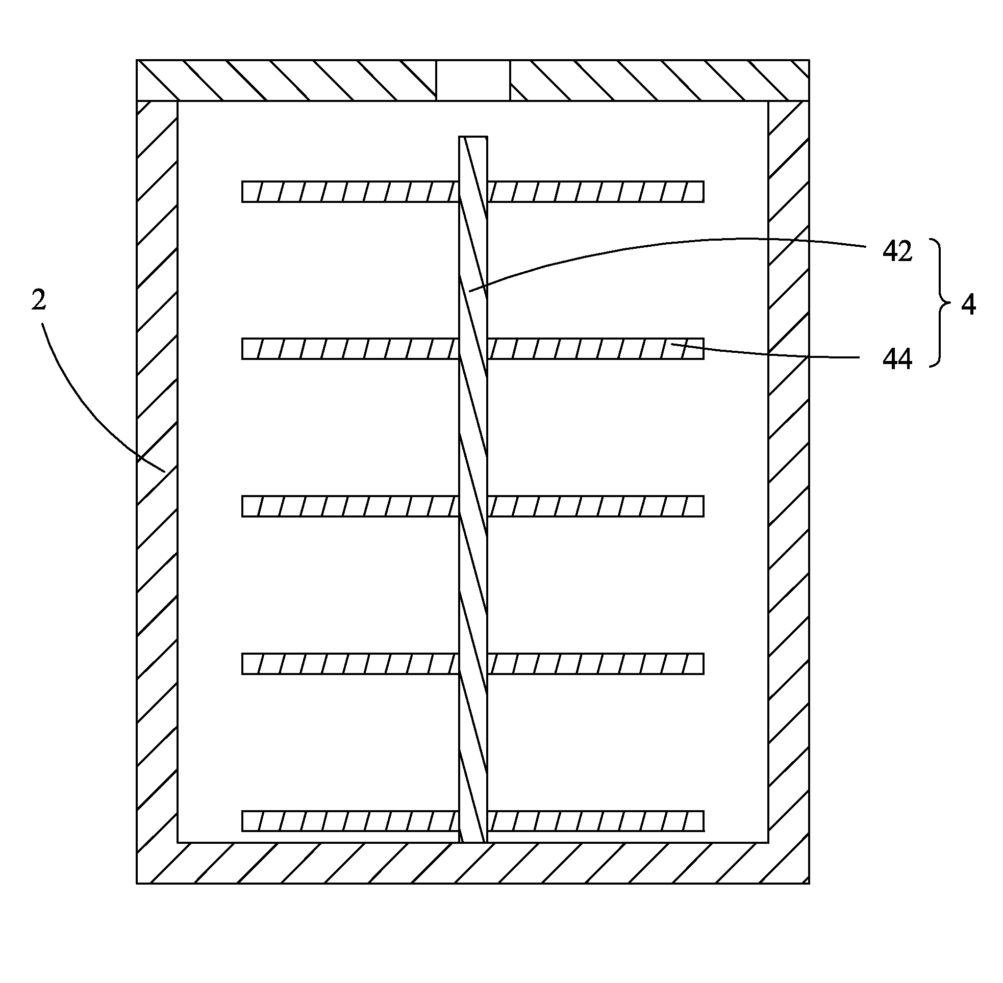
[0047]Referring to FIG. 5, which is a schematic view showing the structure of the present invention, in the instant embodiment, two adjacent ones of the heat dissipative branches 44′ are respectively set at opposite sides of the heat-dissipative trunk 42. In other words, the heat dissipative branches 44′ are arranged to alternately mount to opposite sides of the heat-dissipative trunk 42. This can similarly achieve the same technical efficacy of the present invention.

third embodiment

[0048]Referring to FIG. 6, which is a schematic view showing the structure of the present invention, in the instant embodiment, the heat dissipative branches 44″ are set to extend from an outer surface of the heat-dissipative trunk 42 in an upward inclined manner. This can similarly achieve the same technical efficacy of the present invention.

fourth embodiment

[0049]Referring to FIG. 7, which is a schematic view showing the structure of the present invention, in the instant embodiment, the heat dissipative branches 44′″ are set to extend from an outer surface of the heat-dissipative trunk 42 in a downward inclined manner. This can similarly achieve the same technical efficacy of the present invention.


PUM


Abstract

The present invention provides a heat conduction device included crucible, which includes: a crucible body and a heat conduction device arranged in the crucible body. The heat conduction device has a tree-like configuration, which includes a heat-dissipative trunk and multiple levels of heat dissipative branches mounted to the heat-dissipative trunk. Each level of the heat dissipative branches includes a plurality of branch units and the branch units are arranged to project out from an outer surface of the heat-dissipative trunk. The heat conduction device included crucible of the present invention uses the tree-like heat conduction device arranged in the crucible body to transfer heat in every direction within the crucible body so that during a vapor deposition operation, an organic material received in the crucible body can be heated uniformly thereby avoiding the phenomenon of partial decomposition of the organic material occurring in the prior art technique due to non-uniform heating of the organic material and thus effectively improving the vapor deposition efficiency and vapor deposition performance.

Description

BACKGROUND OF THE INVENTION[0001]1. Field of the Invention[0002]The present invention relates to the field of manufacture of display devices, and in particular to a heat conduction included crucible for vapor deposition performed with an organic material coater.[0003]2. The Related Arts[0004]A flat panel display has a variety of advantages, such as thin device body, low power consumption, and being free of radiation, and is widely used. Flat panel displays that are currently available generally include liquid crystal displays (LCDs) and organic light emitting displays (OLEDs).[0005]The LCDs that are currently available in the market are generally backlighting LCDs, which comprise an enclosure, a liquid crystal display panel arranged in the enclosure, and a backlight module arranged in the enclosure. The operation principle of the liquid crystal display panel is that liquid crystal molecules are arranged between two parallel glass substrates and a drive voltage is selectively applied...

Claims


Application Information

Patent Timeline
Patent Type & Authority Applications(United States)
IPC IPC(8): F27B14/08
CPCF27B2014/0843F27B14/08
Inventor ZOU, QINGHUA
Owner TCL CHINA STAR OPTOELECTRONICS TECH CO LTD
Why Eureka
Try Eureka