IMPLANTABLE MICRO-TEXTURED SCAR INDUCING ePTFE STRUCTURES

a micro-textured, scar-inducing technology, applied in the direction of prosthesis, blood vessels, catheters, etc., to achieve the effect of reducing or eliminating shear motion

Inactive Publication Date: 2015-02-05
LEDERGERBER WALTER J
View PDF7 Cites 2 Cited by
  • Summary
  • Abstract
  • Description
  • Claims
  • Application Information

AI Technical Summary

Benefits of technology

[0015]New and improved bio-implantable textured tubular and sheet structures of un-sintered ePTFE are described. Such micro-textured structures stimulate the robust development of beneficial bio-integrative scar attachment to adnexal soft tissues. When confronted with an inviting ePTFE surface structure, fibroblasts are attracted to it and insinuate themselves by diapedesis into available interstices and secrete liquid collagen monomers within the “forest” of variegated villous remnants of substrate ePTFE. Such deposited monomers of collagen, attract more fibroblasts and are substantively in non-parallel alignment due to the great complexity of the spaces into which they are secreted. Deposited monomers of collagen subsequently “cement in place” by undergoing polymerization and become deep anchorages for maturing scar tissue. Angiogenesis rapidly develops within such scar matrix accelerating its development. Foundational scar adheres to a very complex pristine crystalline surface with unusual tenacity and thus bio-integrates with the ePTFE implant. The greater such surface area and the greater the complexity of such insinuating scar, the more avid the adherence establishing bio-integration. Trials of a variety of textures have shown that optimal fibroblast in-growth, resulting in optimal bio-integrative scar development, is a function of a dense pristine and complex crystalline topology featuring very numerous tattered and shredded surface villi.
[0030]As polymerization of collagen proceeds, scar is incorporated into and onto the complex topography of the hyper-convoluted surface. It adheres intensely to the ePTFE sheet and thereby grossly reduces or eliminates shear motion at the soft tissue interface with the cover.

Problems solved by technology

Such deposited monomers of collagen, attract more fibroblasts and are substantively in non-parallel alignment due to the great complexity of the spaces into which they are secreted.

Method used


Image

  • IMPLANTABLE MICRO-TEXTURED SCAR INDUCING ePTFE STRUCTURES
  • IMPLANTABLE MICRO-TEXTURED SCAR INDUCING ePTFE STRUCTURES
  • IMPLANTABLE MICRO-TEXTURED SCAR INDUCING ePTFE STRUCTURES

Examples


Embodiment Construction

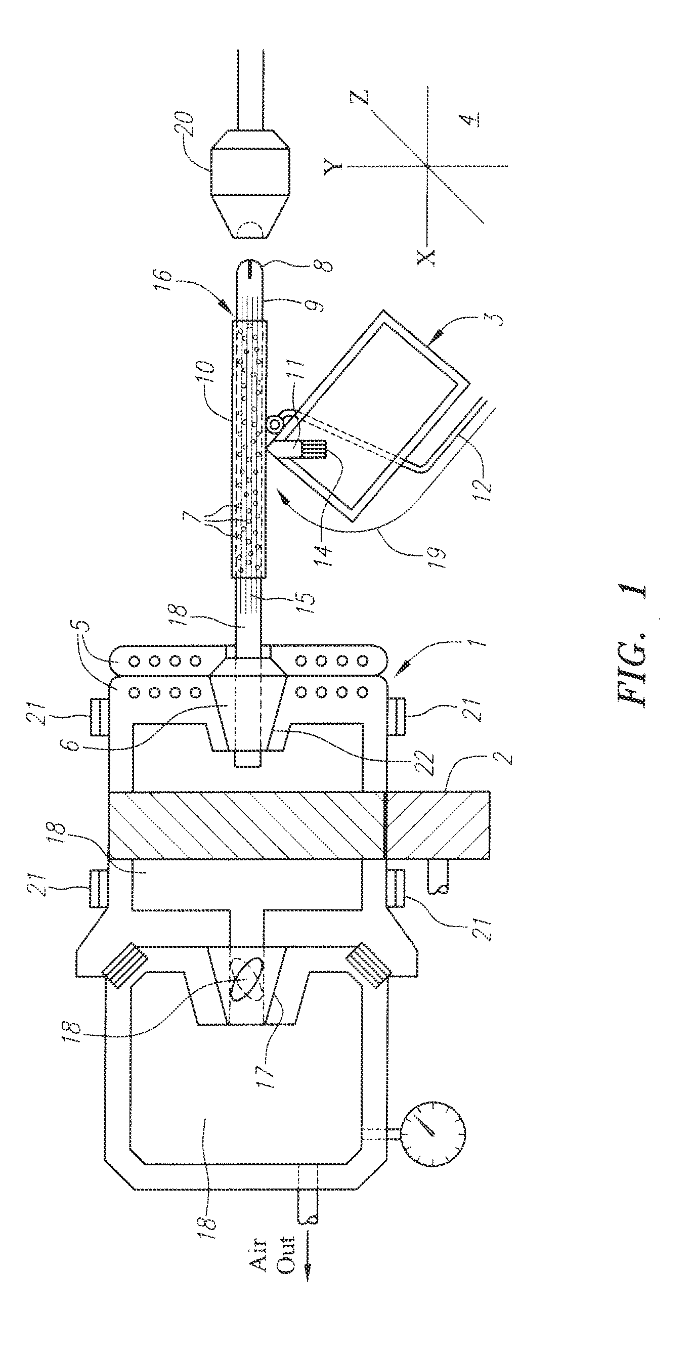
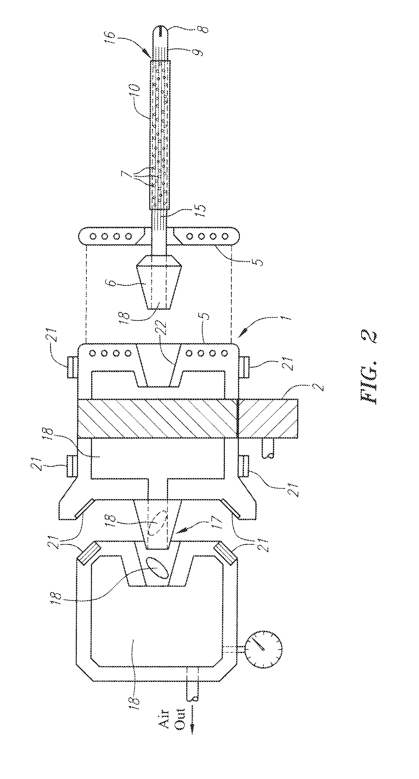
[0039]Referring to FIGS. 1 and 2, the hollow spindle / mandrel assembly 1 is mounted on a lathe which has a computer-controlled variable speed drive 2 and including “forward and reverse”. Programmable rotating and reciprocating motions of the lathe advance the spindle / mandrel assembly 1 into position with respect to the compound motion “RIGDA Tool Assembly”3, which is made to transition along three axes 4 independently. All feed motions are made programmable on the machine. A vacuum source is fitted to the machine. It should be noted that FIGS. 1 and 2 are concept drawings and thus are semi-schematic. As would be appreciated by a person skilled in the art, actual manufacturing drawings very likely would appear different.

[0040]The spindle-mandrel 1 is comprised of a solid high grade stainless steel tank, other structural materials, an adaptive coupling consisting of an integrated hollow conical electromagnetically actuated, and keyed socket chuck 5 which receives the standard precision...


PUM

PropertyMeasurementUnit
depthaaaaaaaaaa
thicknessaaaaaaaaaa
thicknessaaaaaaaaaa

Abstract

Bio-implantable textured tubular and sheet structures of un-sintered ePTFE are described. Such micro-textured structures stimulate robust development of beneficial bio-integative scar attachment to adnexal soft tissues. Methods for texturing one side of an un-sintered extruded ePTFE tube or sheet are also described. A select length of tubing of any thickness or diameter is applied over a matching mandrel and adhesively stabilized thereon by applying intense suction. The texture is made by “RIGDA tooling” into the wall thickness of the material and by removing undesired material by distraction and avulsion tooling and methods assisted by vibration, leaving intact the finished product. Disclosed is an implantable, non-attached, enveloping, conforming and supportive drainage cover for breast and other soft implants. The drainage cover has numerous through and through cut lucencies which allow for liberal ingress and egess of interstitial biologic fluids enabling efficient drainage postoperatively, especially under the influence of active wound suction.

Description

PRIORITY CLAIM [0001]This application is a continuation of application Ser. No. 13 / 275,018, filed Oct. 17, 2011, entitled “Implantable Micro-Textured Scar Inducing ePTFE Structures”, which claims priority to provisional patent Application No. 61 / 408,453, filed Oct. 29, 2010, the contents of which are incorporated by reference herein in their entirety as if fully set forth herein.RELATED APPLICATIONS STATEMENT[0002]This application is related in subject matter to my prior patents including: U.S. Pat. Nos. 4,955,907 (Apr. 11, 1990), 5,282,856 (Feb. 1, 1994), 5,462,781 (Oct. 31, 1995), 5,653,755 (Aug. 5, 1997), 5,779,734 (Jul. 14, 1998), 4,187,390 (Feb. 5, 1980), 6,921,418 (Jul. 26, 2005), 7,041,127 (May 9, 2006), and 7,273,493 (Sep. 25, 2007), which are hereby expressly incorporated by reference in their entirety. No claim of priority is made to any of these prior patents.FIELD OF THE INVENTION[0003]The present inventions related to improved biocompatible implants, and methods for th...

Claims


Application Information

Patent Timeline
Patent Type & Authority Applications(United States)
IPC IPC(8): A61M27/00A61F2/00A61F2/12
CPCA61M27/002A61F2002/0086A61F2/0077A61F2/12B29C2059/027B29C2791/009A61L27/50A61L29/041A61L2400/18A61L2430/04B29C59/021A61F2/04A61F2/0063C08L27/18B29C59/02A61F2/06A61F2/064
Inventor LEDERGERBER, WALTER J.
Owner LEDERGERBER WALTER J
Why Eureka
Try Eureka