Method for avoiding voltage instability in an electrical grid of an offshore wind park

an electrical grid and offshore wind technology, applied in the direction of motors, single network parallel feeding arrangements, power oscillation reduction/prevention, etc., can solve the problems of system voltage instability, voltage collapse, progressive and uncontrollable voltage drop, etc., to avoid voltage instability

Active Publication Date: 2015-02-12
GE RENEWABLE TECH WIND BV
View PDF0 Cites 16 Cited by
  • Summary
  • Abstract
  • Description
  • Claims
  • Application Information

AI Technical Summary

Benefits of technology

[0010]In a first aspect, the invention provides a method for avoiding voltage instability in an electrical grid of an offshore wind park, wherein the offshore wind park electrical grid is connected at a first end of a high voltage alternating current transmission and the main land electrical grid is connected at a second end of the high voltage alternating current transmission, and wherein the wind park has a plurality of wind turbines. The method comprises determining a main land phase angle at or near the second

Problems solved by technology

In known HVAC transmission systems voltage instability problems may occur which may cause a voltage collapse in case of severe disturbances, like deep voltage sags.
A system may enter a state of voltage instability when a disturbance, an increase in load demand, or a change in system conditions, cause a progressive and uncontrollable drop in voltage.
An important factor causing instability is the inability of the power system to meet the demand for reactive power.
At the heart of the problem is usually the voltage drop that occurs when active and reactive power flow through inductive reactances associated with the transmission networ

Method used


Image

  • Method for avoiding voltage instability in an electrical grid of an offshore wind park
  • Method for avoiding voltage instability in an electrical grid of an offshore wind park
  • Method for avoiding voltage instability in an electrical grid of an offshore wind park

Examples


Embodiment Construction

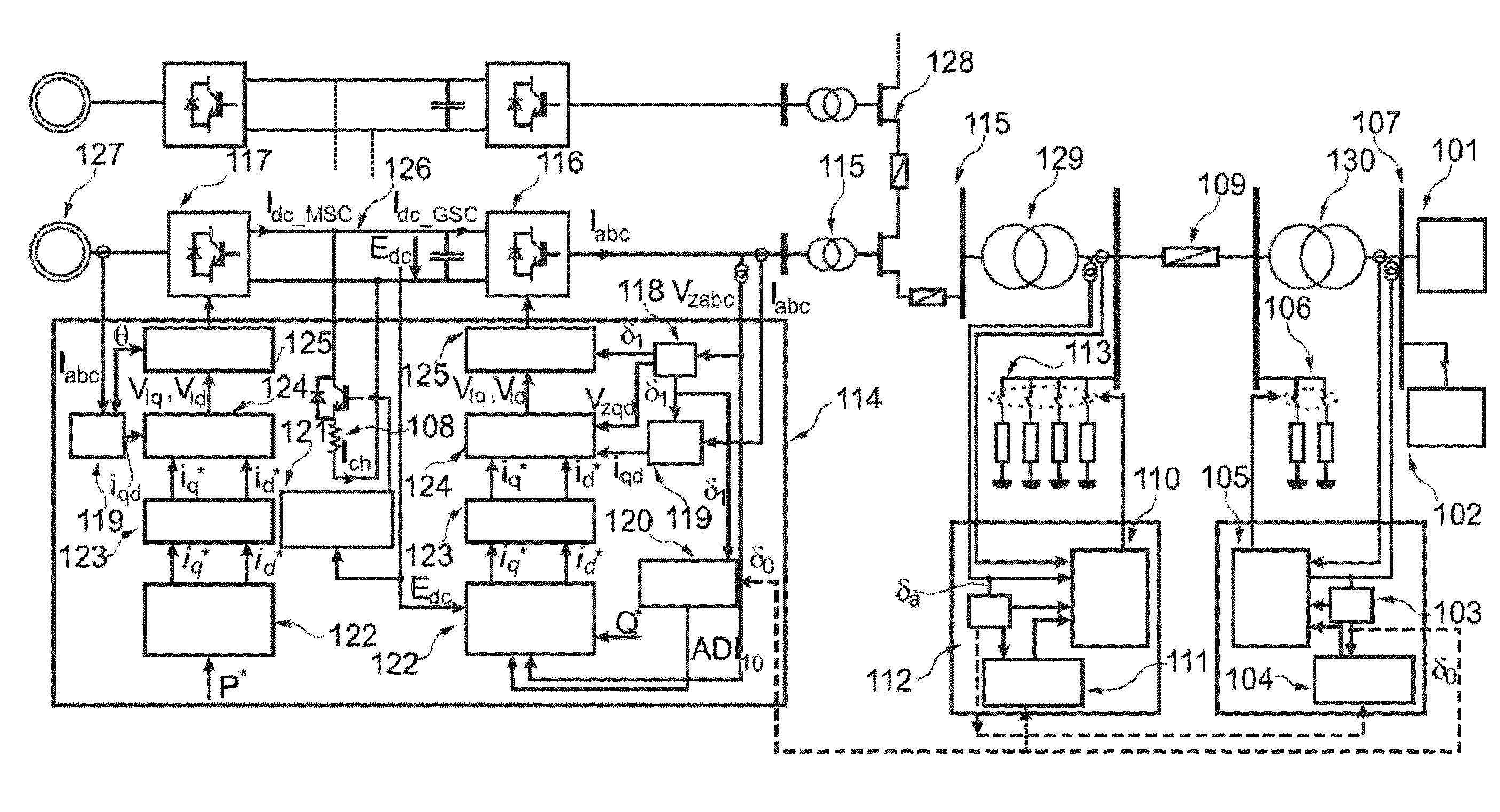
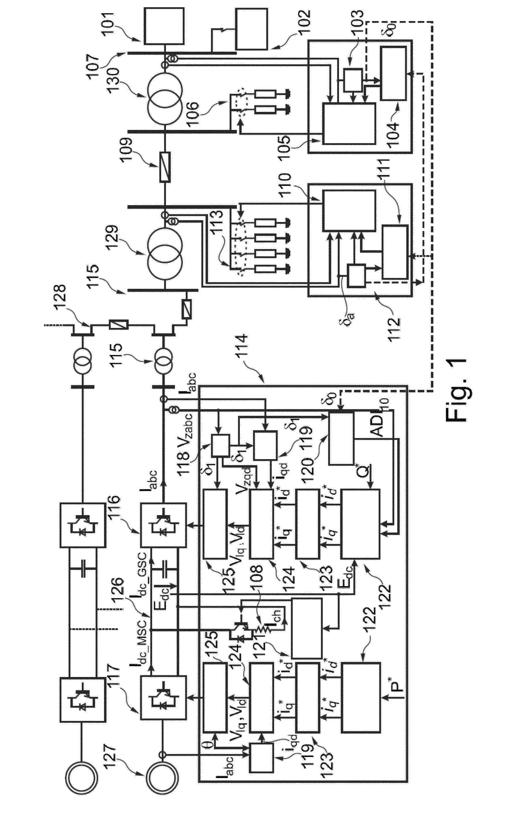
[0022]FIG. 1 shows a schematic representation of a general control scheme of a power system according to an embodiment of the present invention. FIG. 1 shows an offshore wind park comprising a generating unit or wind turbine 127, which in this embodiment may be a permanent magnet synchronous machine (PMSM). The generator of the wind turbine may be connected to a Back-to-Back converter comprising two voltage source converters: machine side converter 117 (MSC) and grid side converter 116 (GSC), and a DC link 126. Further shown is a control unit 114 which controls the wind turbine 127. The already-mentioned elements are connected to a medium voltage transformer 115 and a medium voltage transmission line 128.

[0023]A point of common coupling (PCC) of the offshore wind park 115 connects the offshore wind park with the first end of a high voltage alternating current (HVAC) transmission 109 which comprises a high voltage transformer 129 and AC reactors 113. The AC reactors 113 may be contro...


PUM


Abstract

Method for avoiding voltage instability in an electrical grid of an offshore wind park, the offshore wind park electrical grid being connected at a first end of a high voltage alternating current (HVAC) transmission and the main land electrical grid being connected at a second end of the HVAC transmission, each of the wind turbines being connected to the wind park electrical grid, the method comprises determining a main land phase angle at or near the second end of the HVAC transmission; measuring an individual wind turbine phase angle at one or more wind turbines; determining the difference between each of the measured individual wind turbine phase angles and the main land phase angle; and determining whether the difference between one of the measured individual wind turbine phase angle and the main land phase angle exceeds a threshold phase angle difference.

Description

[0001]This application claims the benefit of European Patent Application EP12382051, filed on Feb. 16, 2012, and of U.S. Provisional Patent Application Ser. No. 61 / 624,884, filed on Apr. 16, 2012.[0002]The present invention relates to methods for avoiding voltage instability in offshore wind parksBACKGROUND ART[0003]Modern wind turbines are commonly used to supply electricity into the electrical grid. Wind turbines of this kind generally comprise a rotor with a rotor hub and a plurality of blades. The rotor is set into rotation under the influence of the wind on the blades. The rotation of the rotor shaft either directly drives the generator rotor (“directly driven”) or through the use of a gearbox.[0004]An important trend in the field of wind turbines is to place the turbines in offshore wind parks. These wind parks comprise a plurality of wind turbines and a local wind park grid. This wind park grid may be connected to an onshore electrical grid through a High Voltage Alternating ...

Claims


Application Information

Patent Timeline
IPC IPC(8): H02J3/24F03D7/00F03D9/00
CPCH02J3/24F03D7/00F03D9/005F03D7/0284F05B2240/95F03D9/257F03D7/048H02J2300/28H02J3/381Y02E10/727Y02E10/72Y02E10/76H02J3/48G01R25/005G05B15/02
Inventor GOMIS BELLMUNT, ORIOLARAGUES PENALBA, MONICA
Owner GE RENEWABLE TECH WIND BV
Why Eureka
Try Eureka