Method and device for measuring currents or magnetic fields using hall sensors

Active Publication Date: 2015-02-12
FRAUNHOFER GESELLSCHAFT ZUR FOERDERUNG DER ANGEWANDTEN FORSCHUNG EV
View PDF5 Cites 0 Cited by
  • Summary
  • Abstract
  • Description
  • Claims
  • Application Information

AI Technical Summary

Benefits of technology

[0016]The proposed method and the associated apparatus can be applied particularly advantageously for fast current measurement, for example, in electric drives, as was mentioned briefly in the introduction to

Problems solved by technology

However, shunt resistors cannot be used if, for example, a galvanically isolated measurement is to be made, if the current-carrying conductor either must not or cannot be disconnected, or if large enough currents can occur in the system such that a shunt would be destroyed or damaged.
With this solution however, volumes and costs are relatively high, because depending on the dimensioning a large amount of magnetically active material is needed.
The main problem in measuring current with Hall sensors without a magnetic core, however, is the relatively high sensor offset in relation to the signal magnitude.
However, the use of the spinning current principle limits the measuring frequency that can be achieved, due to the transient oscillati

Method used


Image

  • Method and device for measuring currents or magnetic fields using hall sensors
  • Method and device for measuring currents or magnetic fields using hall sensors
  • Method and device for measuring currents or magnetic fields using hall sensors

Examples


Embodiment Construction

[0008]This object is achieved with the method and the apparatus in accordance with claims 1 and 7. Advantageous configurations of the method and the apparatus form the subject matter of the dependent claims or can be inferred from the following description together with the exemplary embodiments.

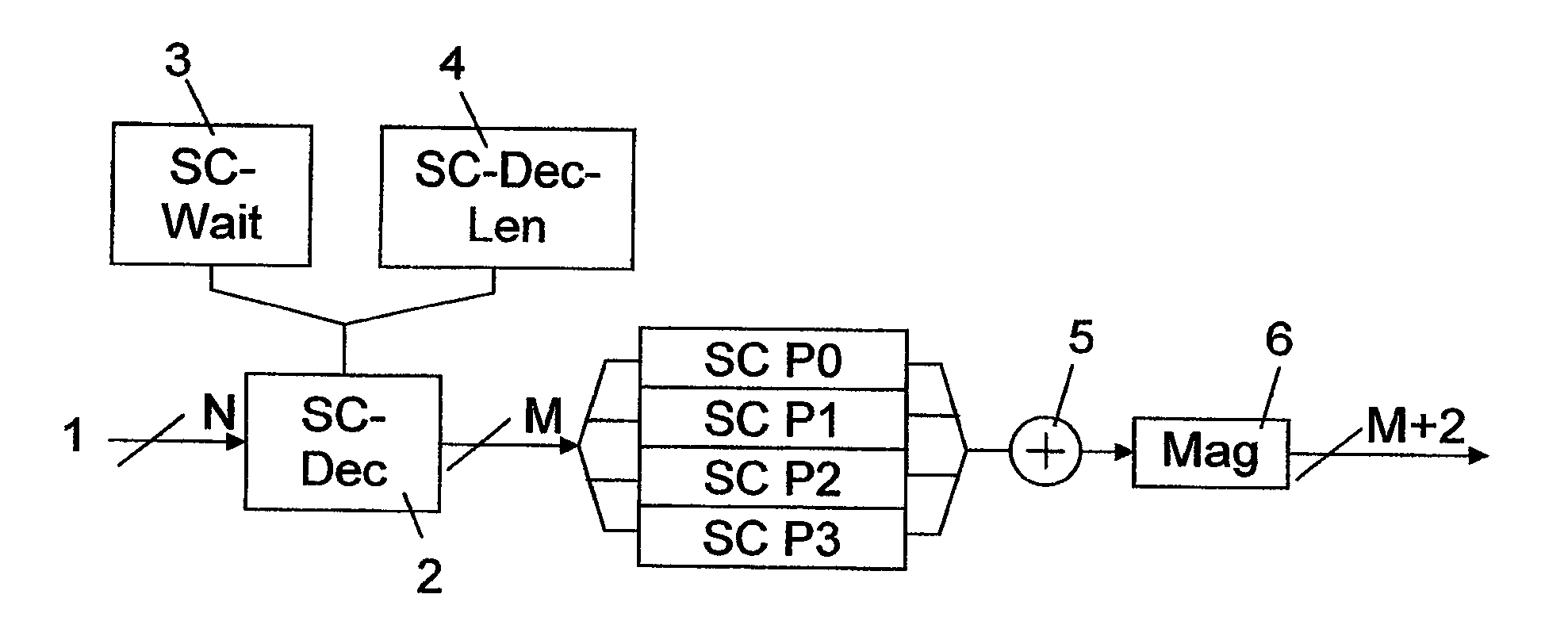
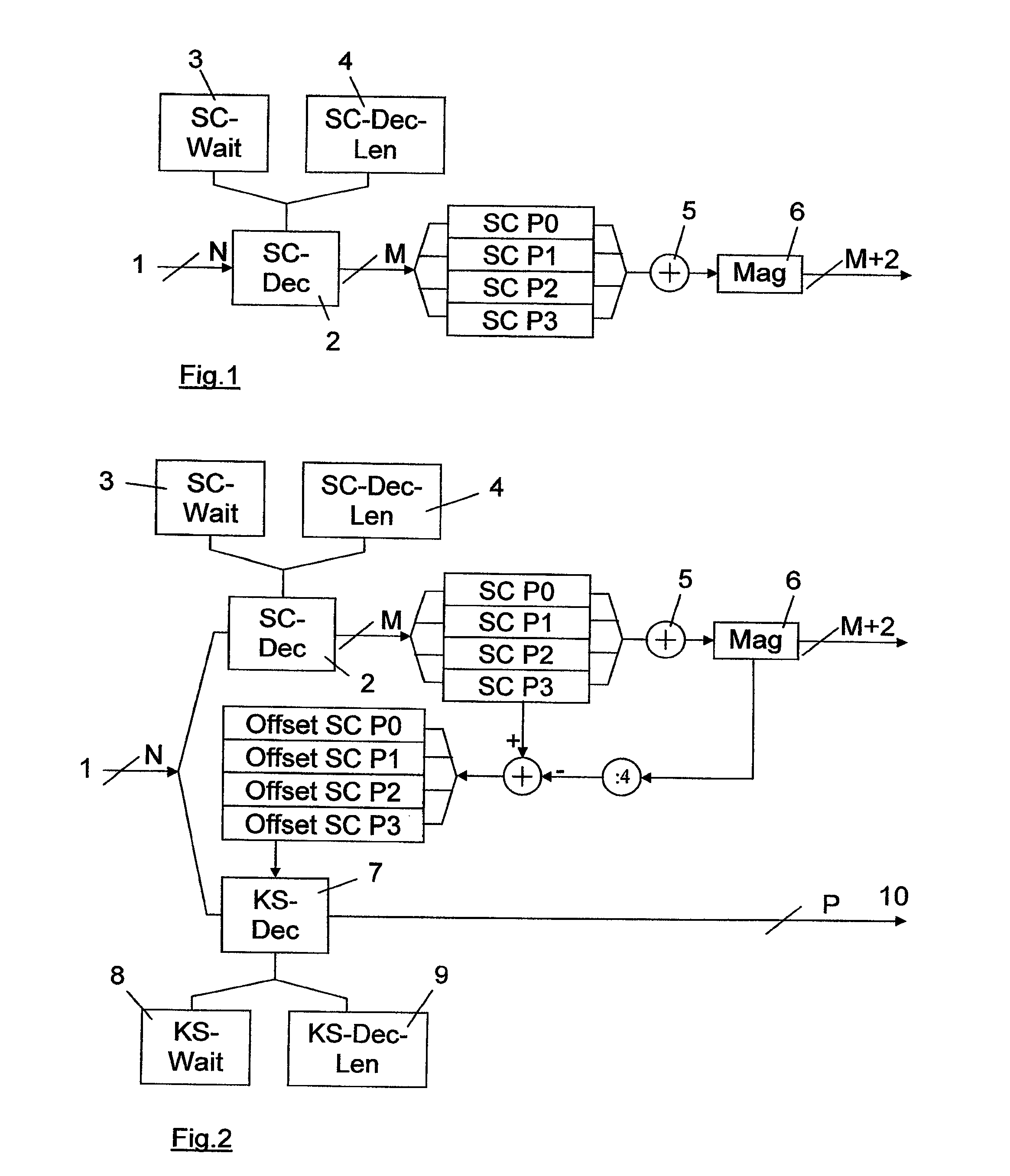
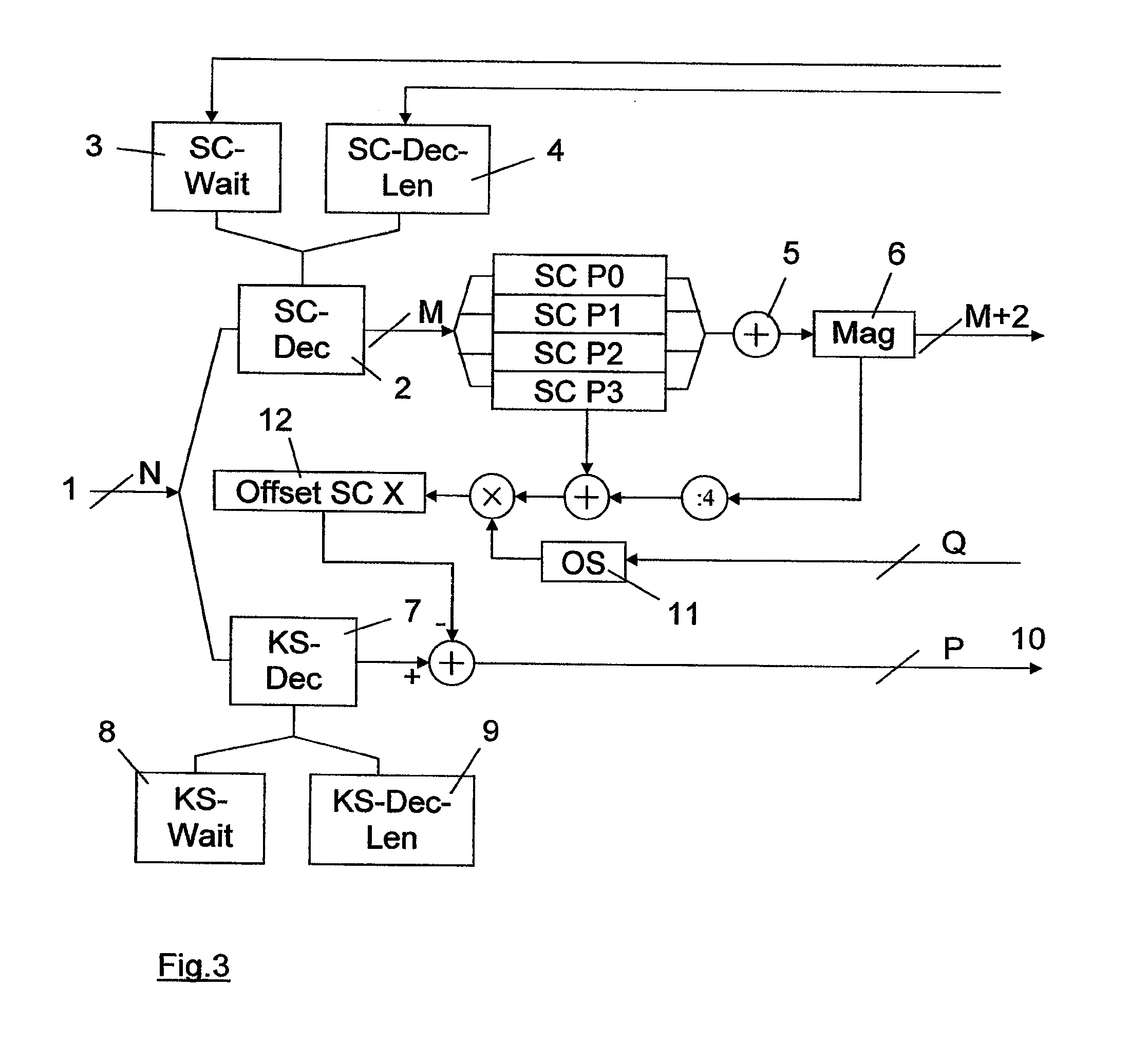
[0009]In the proposed method the Hall effect sensor is operated with spinning current technology, for example with two or four phases. In principle, it is possible to operate the Hall sensor with N phases, where N≧2. In the method, sensor signals from the Hall sensor are converted into digital signals with an analogue-to-digital converter, the digital signals are read from the analogue-to-digital converter and combined over a first period for each spinning current phase to obtain a first sample. The first samples of the spinning current phases of a spinning current cycle are added together to form a spinning current measurement value of the current or magnetic field. The sensor signals or ou...


PUM


Abstract

The present invention relates to a method and a device for measuring currents or magnetic fields using at least one Hall sensor, which is operated with spinning current technology. In addition to first sample values for calculating a spinning current measurement value (6), second sample values are formed from the digitally converted sensor signals (1) of the Hall sensor in the method. The second sample values are formed over shorter periods of time (9) and are corrected with an offset, which is calculated from the spinning current measurement value (6) and the first sample values. In addition to the precise spinning current measurement value (6), fast offset-corrected measurement values (10) of the magnetic field or current are obtained using the method and the associated device, without elaborate calibration or additional analogue circuitry expenses.

Description

TECHNICAL FIELD OF APPLICATION[0001]The present invention relates to a method and a device for measuring currents or magnetic fields having at least one Hall sensor, which is operated with spinning current technology, and in which sensor signals from the Hall sensor are converted into digital signals with an analogue-to-digital converter, the digital signals are read from the analogue-to-digital converter and for each spinning current phase are combined over a first period in order to obtain a first sample, and the first samples of the spinning current phases of a spinning current cycle are summed to form a spinning current measurement value of the current or magnetic field.PRIOR ART[0002]Current measurement in electric drives has long been dominated by shunt resistors. These are usually easy to use, small in size and allow rapid signal analysis. However, shunt resistors cannot be used if, for example, a galvanically isolated measurement is to be made, if the current-carrying conduc...

Claims


Application Information

Patent Timeline
IPC IPC(8): G01R15/20G01R33/07
CPCG01R33/07G01R15/202G01D5/142G01R33/0017G01R33/075
Inventor HACKNER, MICHAELHOHE, HANS-PETERSAND, MARKUS
Owner FRAUNHOFER GESELLSCHAFT ZUR FOERDERUNG DER ANGEWANDTEN FORSCHUNG EV
Why Eureka
Try Eureka