
Wind turbine having flow-aligned blades

a technology of flow-aligned blades and wind turbines, which is applied in the direction of wind motors, wind motor control, reaction engines, etc., can solve the problems of high turbine rotation rate, and the assumption underlying the foregoing design approach is open to question

Active Publication Date: 2015-02-12
MCCUNE EARL
View PDF10 Cites 1 Cited by
  • Summary
  • Abstract
  • Description
  • Claims
  • Application Information

AI Technical Summary

Benefits of technology

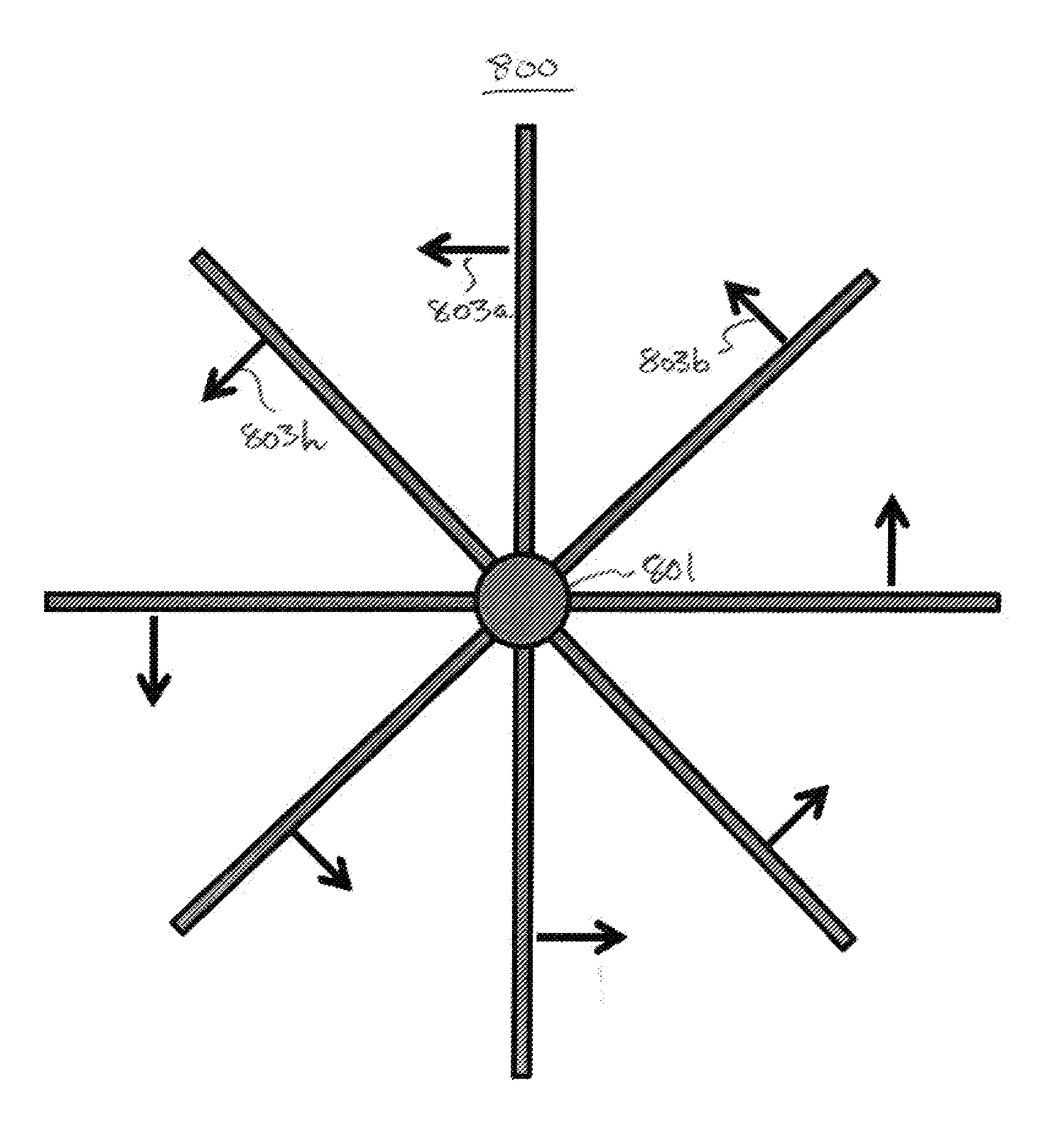
The technical effect of this patent text is to have the lift force from the blade airfoil always be normal to the shaft torque, which maximizes energy conversion. This is achieved by aligning the airfoil chord with the actual wind direction and slowing down the turbine rotation rate to prevent blade twist. As a result, the tip speed ratio, defined as the ratio of tip speed to fluid speed, is less than one, which eliminates any hazard to wildlife. The control problem simplifies to adjusting the blade angle of attack to keep the lift constant across varying wind speeds. This fail-safe condition ensures that the wind turbine operates safely without the need for overspeed control.

Problems solved by technology

The fast moving rotor blades also pose a distinct hazard to birds and other flying creatures.
On closer examination, however, the assumptions underlying the foregoing design approach appear to be open to question.
Furthermore, higher wind speeds cause higher turbine rotation rates, resulting in a safety hazard and necessitating complexity in turbine control design to address this hazard.

Method used


Image

  • Wind turbine having flow-aligned blades
  • Wind turbine having flow-aligned blades
  • Wind turbine having flow-aligned blades

Examples


Embodiment Construction

[0037]Summary

[0038]The present turbine rotor blade design satisfies the following objectives:[0039]1. A turbine rotor (blades around a shaft) which can provide constant torque irrespective of the wind speed[0040]2. Consistent energy conversion at all wind speeds, or operating fluid speeds[0041]3. Slow rotation: No safety problem from fast turbine rotation[0042]4. Low noise from blade vortex turbulence[0043]5. Simplified control to lower cost

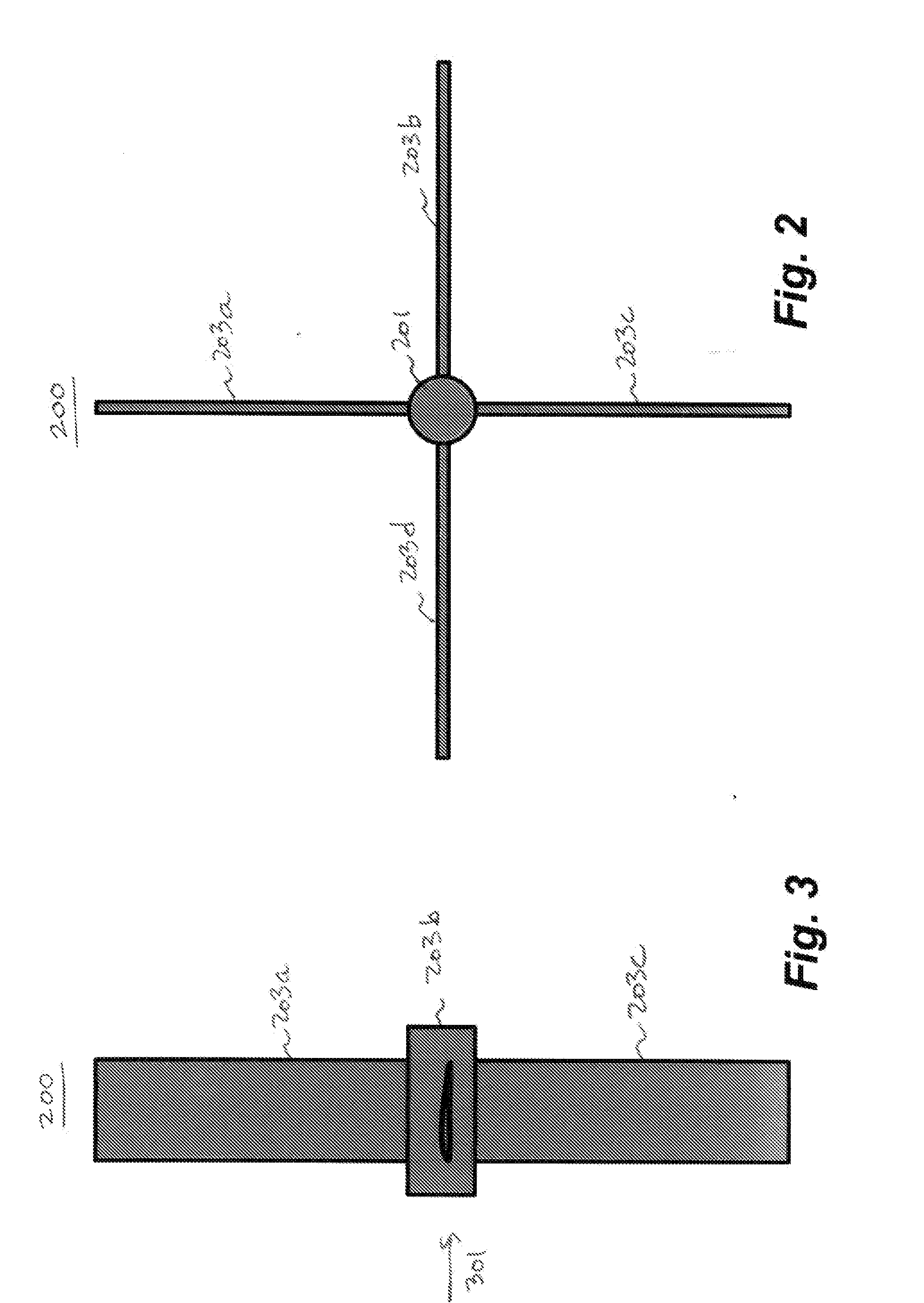
[0044]One principal objective is to have the lift force from the blade airfoil always be normal to the shaft torque. This condition necessarily maximizes energy conversion. This objective may be achieved by a) having the airfoil chord always aligned to the actual wind (operating fluid) direction, subject only to small angle of attack variations, and b) slowing the turbine rotation rate so that no blade twist is needed. As a result, blade tip speed due to shaft rotation is less than the wind (operating fluid) speed, and preferably much less. That ...


PUM


Abstract

A wind turbine blade is configured such that the lift force from the blade airfoil is always normal, or nearly normal, to the shaft torque. This condition maximizes energy conversion. This objective may be achieved by a) having the airfoil chord always aligned to the actual wind direction (subject only to small angle of attack variations), and b) slowing the turbine rotation rate so that no blade twist is needed. As a result, blade tip speed due to shaft rotation is less than the wind speed, and preferably much less. This low tip speed eliminates any hazard to birds. The lift force from the blade airfoil directly drives the torque on the shaft, so the control problem simplifies to adjusting the blade angle of attack to keep the lift constant across varying wind speeds. For most airfoils, a slightly negative angle of attack results in zero lift, so this simple approach has a ready fail-safe condition. This fail-safe condition is operable up to very high wind speeds, eliminating any need to provide for turbine overspeed control. The same teachings are equally applicable to water turbines and other types of turbines.

Description

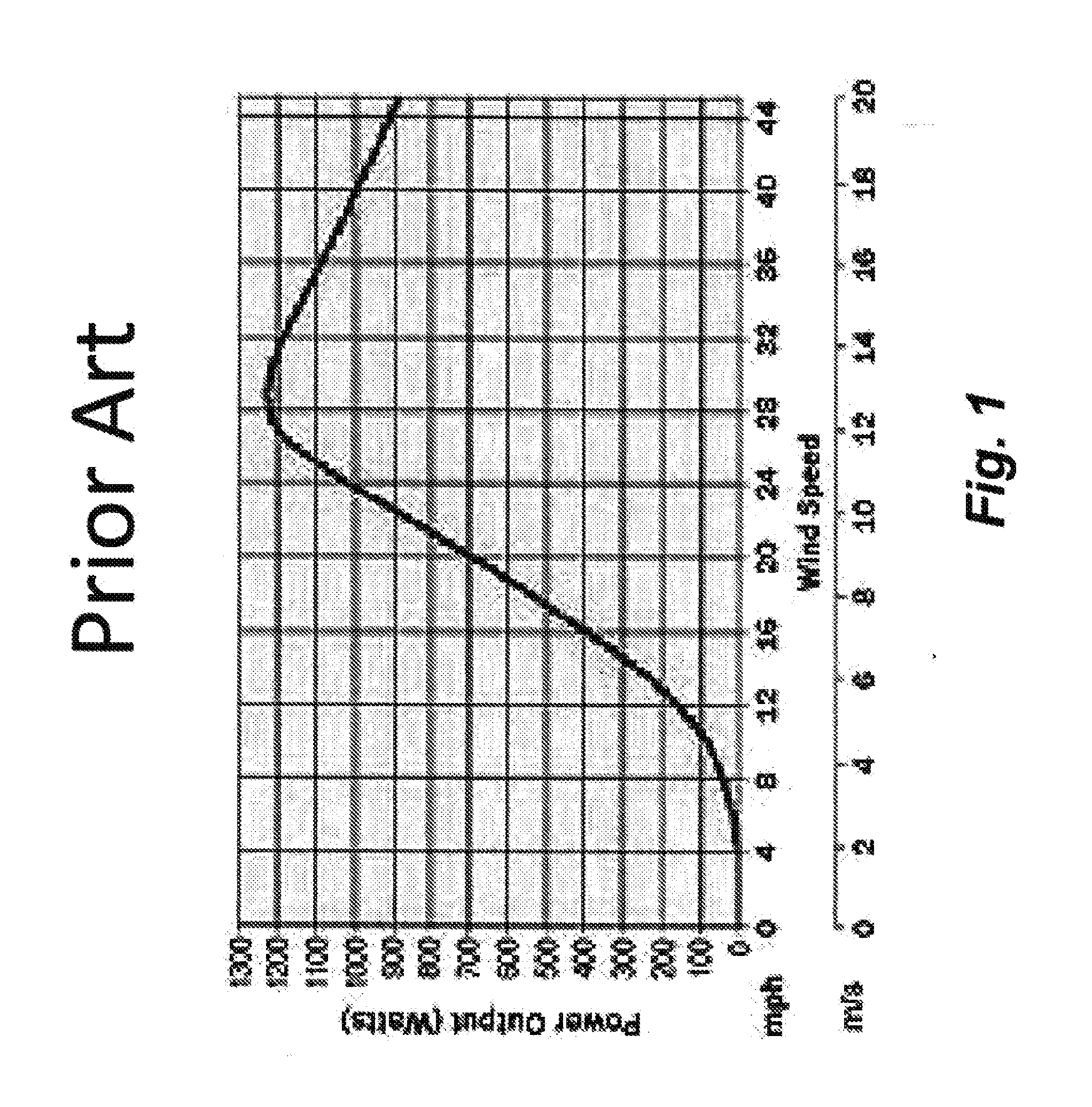
RELATED APPLICATIONS[0001]This application claims benefit of U.S. Application 61 / 391,198 titled WIND TURBINE DESIGN AND MANUFACTURE filed 7 Oct. 2010, incorporated herein by reference.BACKGROUND[0002]Existing wind turbine designs look very much like aircraft propellers. Underlying this resemblance is the apparent assumption that the wind turbine problem—extracting energy from the wind—is the dual of the aircraft propulsion problem. Further to this assumption, existing wind turbines rotate fairly rapidly, with blade tip speeds around 200 miles per hour. Noise from the tip vortex is a necessary result. The fast moving rotor blades also pose a distinct hazard to birds and other flying creatures.[0003]On closer examination, however, the assumptions underlying the foregoing design approach appear to be open to question. In particular, aircraft propellers are designed to convert torque from the engine into a forward-directed lift force. One byproduct of this process is “propeller wash,” a...

Claims


Application Information

Patent Timeline
Patent Type & Authority Applications(United States)
IPC IPC(8): F03D1/06
CPCF03D1/0633F03D1/0625F05B2240/313F03D7/0224F03D7/0276F05B2240/2211F03D7/0236Y02E10/72F03D1/0601
Inventor MCCUNE, EARL
Owner MCCUNE EARL
Learn More