Fuel cell with segregated electrolyte distribution and method for making the same

a fuel cell and electrolyte technology, applied in the field of fuel cells, can solve problems such as the challenge of controlling local ionomer distribution, and achieve the effects of maximizing energy conversion, improving performance, and minimizing interaction

Inactive Publication Date: 2019-06-11
GM GLOBAL TECH OPERATIONS LLC
View PDF3 Cites 0 Cited by
  • Summary
  • Abstract
  • Description
  • Claims
  • Application Information

AI Technical Summary

Benefits of technology

[0003]A fuel cell membrane electrode assembly typically includes a polymer electrolyte membrane sandwiched between an anode and a cathode. During fuel cell operation, a fuel gas, such as hydrogen, is oxidized on the anode while an oxidant gas, such as oxygen, is reduced on the cathode. The electrochemical redox reactions on the anode and cathode are generally catalyzed by a metal catalyst, such as platinum. Electricity can be generated from such electrochemical reactions in a fuel cell at a high efficiency. A reactant gas (either the fuel gas or the oxidant gas) has a fast transport rate and minimal kinetic barrier to reach the reactive sites in a thin electrode layer, resulting in higher current density at a given cell voltage. Additionally, a catalyst is typically distributed uniformly through the single layer electrode configuration to ensure uniform current distribution.SUMMARY
[0005]In the fuel cell electrode made by using the method described below, the ionomer is strongly associated with carbon nanotubes (CNT) to minimize the interaction between the ionomer and the platinum surface. Instead of mixing the catalyst with the ionomer together in one step, the ionomer is first associated with the CNTs in a separate container before adding the catalyst. During the pre-mix step, a poor solvent for both CNT and ionomer is used to generate a strongly associated CNT-ionomer composite that is harvested for subsequent ink preparation. This composite becomes well-dispersed in water (which turns black) and is stable for several days. The strong association between CNT and ionomer occurs because ionomer wraps around the CNTs. Fuel cells with cathodes made using this approach showed improvements in performance during testing at high-current densities (i.e., 40-60 mV at 2.5 A / cm2). Specifically, the presently disclosed electrode made by the method described below balances proton conduction and oxygen transport in order to maximize energy conversion during the electrochemical reaction in the fuel cell.

Problems solved by technology

Moreover, because the ionomer is relatively fluid under fuel cell operating conditions, it is challenging to control local ionomer distribution.

Method used


Image

  • Fuel cell with segregated electrolyte distribution and method for making the same
  • Fuel cell with segregated electrolyte distribution and method for making the same

Examples


Embodiment Construction

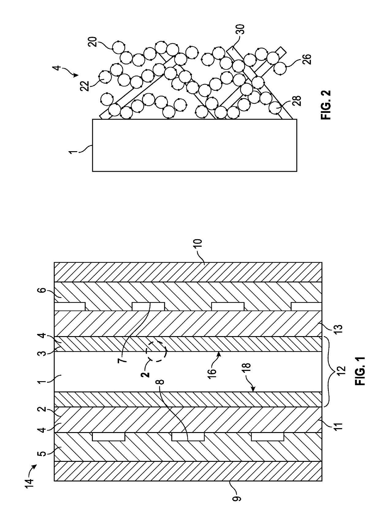
[0017]FIG. 1 is a schematic cross-sectional view of an exemplary fuel cell 14 including a membrane electrode assembly (MEA) 12 having a layered electrode as described in detail below. The MEA 12 is sandwiched between a first gas diffusion layer 11 and a second gas diffusion layer 13. The membrane assembly comprises a proton-conductive polymer electrolyte membrane (PEM) 1 sandwiched between an anode layer 3 and a cathode layer 2. Each of the anode layer 3 and the cathode layer 2 is an electrode 4.

[0018]The PEM 1 may also be referred to as the proton exchange membrane and defines a first membrane surface 16 and a second membrane surface 18 opposite the first membrane surface 16. The anode layer 3 is disposed on the first membrane surface 16, and the cathode layer 2 is disposed on the second membrane surface 18. The PEM 1 may include any polyelectrolyte suitable for the fuel cell 14. The polymer electrolyte may include hydrocarbon- and fluorocarbon-based resins. Hydrocarbon-based elect...


PUM

PropertyMeasurementUnit
diameteraaaaaaaaaa
diameteraaaaaaaaaa
temperatureaaaaaaaaaa

Abstract

A method of making a fuel cell including the following steps: comprising: (a) mixing carbon nanotubes (CNT) with an initial dispersion, wherein the initial dispersion includes an ionomer; (b) heating and stirring the initial dispersion to form a CNT-ionomer composite suspension; (c) after forming the CNT-ionomer composite suspension, mixing the CNT-ionomer composite suspension with an electrode catalyst solution to form an electrode ink, wherein the electrode catalyst solution includes a carbon black powder and a catalyst supported by the carbon black powder; and (d) coating a proton exchange membrane with the electrode ink to form the fuel cell electrode.

Description

GOVERNMENT FUNDING[0001]This invention was made with government support under contract number DE-EE0007271 awarded by Department of Energy. The government has certain rights in the invention.INTRODUCTION[0002]The present disclosure relates to fuel cells and, more particularly, to fuel cell electrodes with a segregated electrolyte distribution and methods for making the same.[0003]A fuel cell membrane electrode assembly typically includes a polymer electrolyte membrane sandwiched between an anode and a cathode. During fuel cell operation, a fuel gas, such as hydrogen, is oxidized on the anode while an oxidant gas, such as oxygen, is reduced on the cathode. The electrochemical redox reactions on the anode and cathode are generally catalyzed by a metal catalyst, such as platinum. Electricity can be generated from such electrochemical reactions in a fuel cell at a high efficiency. A reactant gas (either the fuel gas or the oxidant gas) has a fast transport rate and minimal kinetic barri...

Claims


Application Information

Patent Timeline
Patent Type & Authority Patents(United States)
IPC IPC(8): H01M8/10B01J47/12H01M8/1004H01M8/1032H01M8/1039C08J5/22B01J39/20H01M4/86H01M4/92H01M4/88H01M8/1018
CPCH01M4/8892B01J39/20B01J47/12C08J5/225H01M4/8663H01M4/8673H01M4/8828H01M4/926H01M8/1004H01M8/1032H01M8/1039H01M4/881H01M2008/1095H01M8/1007Y02P70/50Y02E60/50
Inventor KONGKANAND, ANUSORNCARPENTER, MICHAEL K.
Owner GM GLOBAL TECH OPERATIONS LLC
Why Eureka
Try Eureka