3-D sola cell device for a concentrated photovoltaic system

a photovoltaic system and concentrated technology, applied in semiconductor devices, pv power plants, thermal-pv hybrid energy generation, etc., can solve the problems of low solar energy efficiency, implicit unreliability of components, etc., to improve reliability, reduce production costs, and high solar energy efficiency

Active Publication Date: 2014-12-23
KIM GERALD HO +1
View PDF13 Cites 1 Cited by
  • Summary
  • Abstract
  • Description
  • Claims
  • Application Information

AI Technical Summary

Benefits of technology

[0008]A low cost design for a concentrated photovoltaic (CPV) solar cell device is developed with a 3-D solar cell structure that eliminates the need for sun-ray tracking and with improved electricity conversion efficiency for cooling solar cells. The 3-D solar cell structure can be built with conventional monocrystalline or polycrystalline silicon or with multi-junction III-V solar material, joining two or more solar cell segments perpendicular to a base solar cell. This structure is able to collect all incident sunlight from sunrise to sunset. Since the CPV solar cell system collects a large area of solar power into a small solar cell footprint, the design incorporates liquid cooling on the back side of the solar cell. The effective cooling of the solar cell will increase the electricity conversion efficiency and the three-dimensional solar cell structure permits the collection of all incident sunlight without the need to track the sun's position. The design also uses the spent cooling liquid as a source of thermal energy for generating hot-water. By collecting both thermal and electrical energy, the 3-D solar cell design can maximize the total solar energy conversion.
[0009]The concentrated photovoltaic solar cell device has a focusing lens element that focuses all solar energy into a 3-D solar cell structure with a liquid cooling feature on the backside. The 3-D construction of the solar cell eliminates the needs of mounting a tracking system since the 3-D solar cell structure captures all sunlight throughout the day.
[0011]The most unique feature of the 3-D solar cell device is that it captures all sunlight from any latitudinal or longitudinal change in solar position without moving the 3-D solar cell device. Most current CPV solar cell systems move their focusing lens to face directly to sunlight so the solar focus can be projected onto a solar cell. The new 3-D solar cell device solves the tracking problem of solar movement by building a special 3-D solar cell structure. A 2-D solar cell structure has a solar cell laid on a flat surface and a tracking system moves the solar cell normal to the incident sunlight; however, the 3-D solar cell structure adds to the 2-D solar cell structure in the out-of-the-plane direction to capture all sunlight that is not normal to the solar cell structure. The 3-D solar cell structure eliminates the needs of solar tracking system to improve reliability and lower production cost.
[0012]Another feature of the 3-D solar cell structure is that it can be designed with a corner-cube configuration to compensate for all latitudinal and longitudinal changes due to seasonal and daily solar movements. The corner-cube configuration has the advantage of collecting sunlight from impinging on any angle and the out-of-the plane solar cell is highly effective at collecting sunlight during the sunrise and sunset periods. All 3-D solar cell devices are incorporated with a liquid cooling channel at the back of the solar cells so maximum solar intensity can be used for generating solar electricity.
[0013]The new CPV solar cell system combining the special 3-D solar cell structure and liquid cooling can achieve high solar energy efficiency and lower manufacturing costs. The CPV solar cell system is designed to deliver a lower cost system with maximum solar energy conversion efficiency since the liquid cooling keeps the operating temperature of the solar cell at reasonable levels. The cooling liquid of the 3-D solar cell device can be recycled to warm up a hot-water tank in a household. Once the liquid warms from the active 3-D solar cell device, the liquid is circulated to a heat-exchanger for cooling down by cold water. The cold water heats up and the water temperature in the hot-water tank rises as it accumulate the converted solar thermal energy. The hot water in the tank can be used for a variety of household uses, including heating and washing.

Problems solved by technology

The current problem with CPV solar designs, however, is that the solar cell has to face the solar rays directly to generate adequate amounts of electricity.
Typically, the tracking system is a relatively expensive component.
Furthermore, its mechanical nature makes it an implicitly unreliable component over many years of continuous operation.
Because the thermal energy is also absorbed into the solar cell, a large heat sink is often used to cool off the solar cell in CPV designs and the solar cell loses its efficiency as the temperature rises beyond a certain threshold.

Method used


Image

  • 3-D sola cell device for a concentrated photovoltaic system
  • 3-D sola cell device for a concentrated photovoltaic system
  • 3-D sola cell device for a concentrated photovoltaic system

Examples


first example

Illustrative First Example

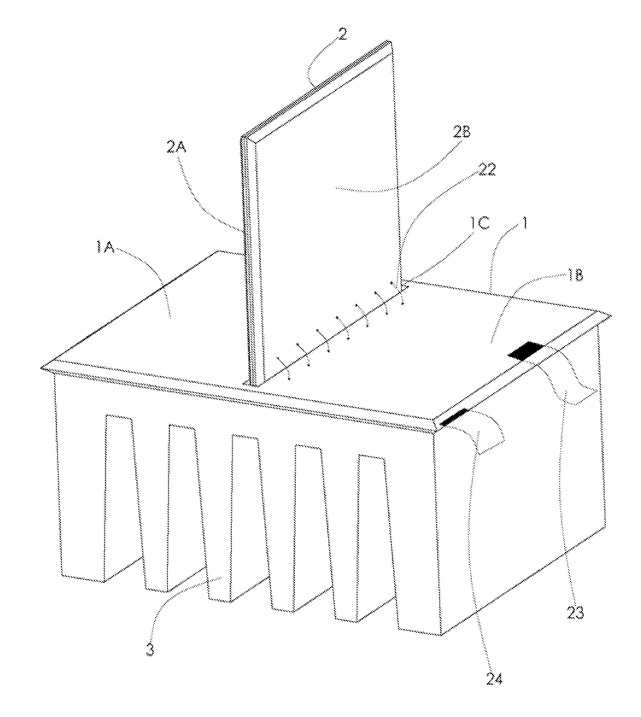
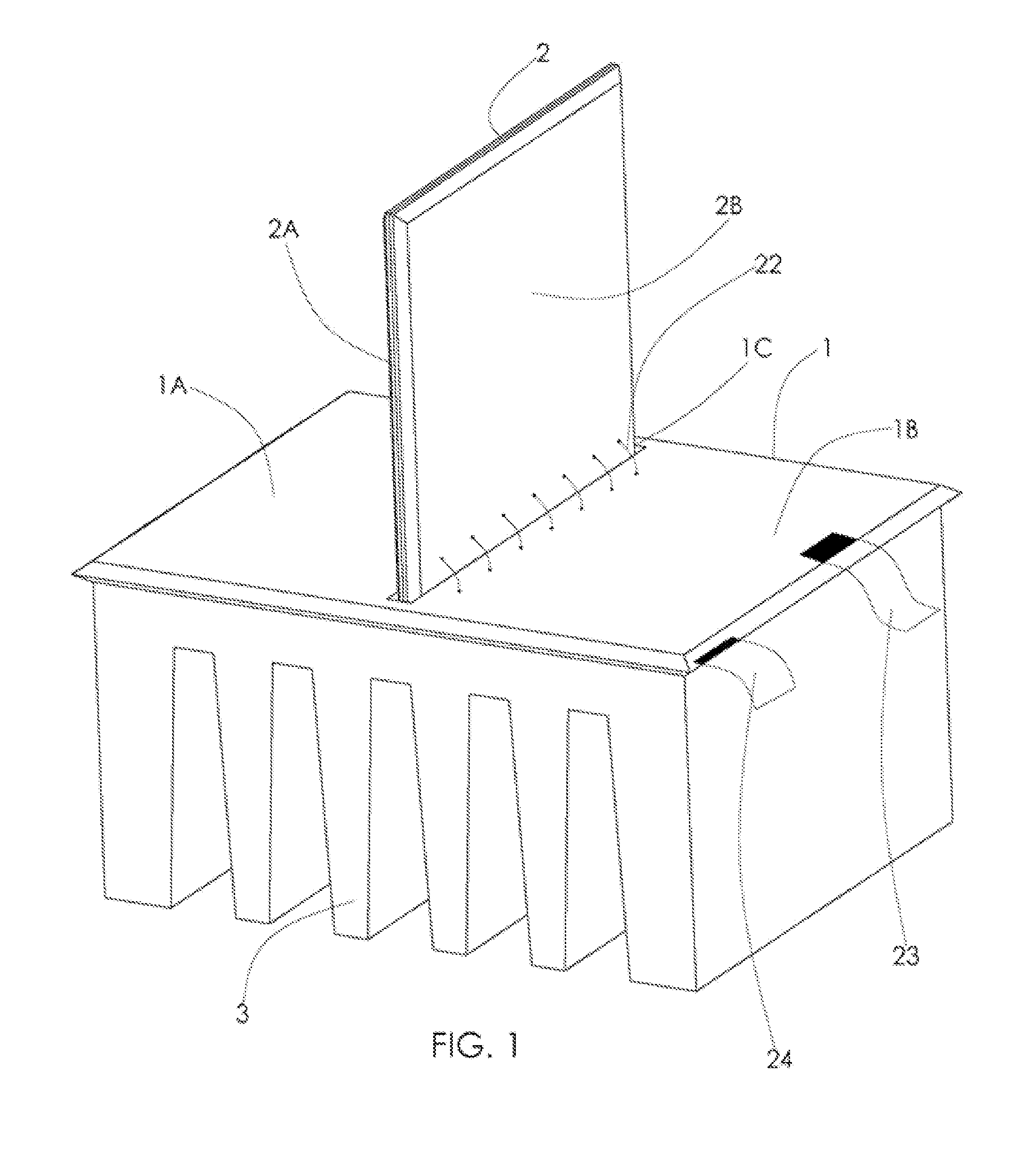
[0066]FIG. 1 shows an assembly view of a 3-D solar cell device. The 3-D solar cell structure comprises a base solar cell chip 1, a vertical solar cell chip 2 and a mounting block 3. The base solar cell chip 1 comprises a face of an n-type solar cell 1A and 1B, and a groove 10. The vertical solar cell chip 2 comprises a face of n-type solar cell 2A and a face of an n-type solar cell 2B. The vertical solar cell chip 2 can be formed by bonding two pieces of a solar cell back-to-back so that the n-type face of the vertical solar cell 2 shows on the n-type face of 2A and 2B. Then, the vertical solar cell chip 2 is interconnected to the groove 10 to form a perpendicular vertical wall shown in FIG. 1. The n-type faces 1A, 1B, 2A and 2B are connected by conducting wires 22 for an electrical connection on all n-type surfaces. Sunlight is focused by a lens element such as a convex or Fresnel lens to the faces of 1A, 1B, 2A and 2B as the sun travels from east to west....

second example

Illustrative Second Example

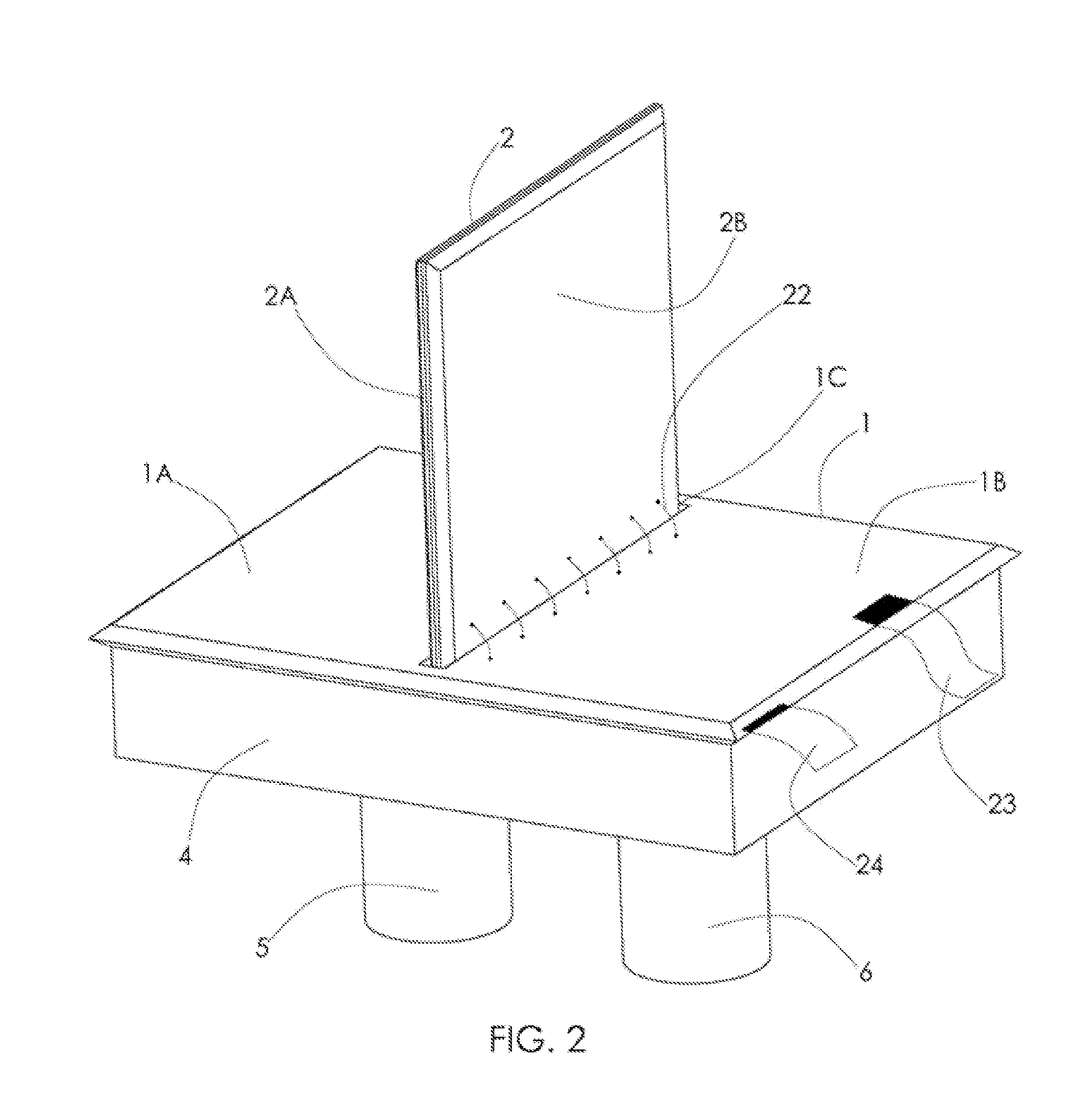
[0067]FIG. 2 shows an assembly view of a 3-D solar cell device with liquid cooling channels attached on the backside of all solar cell surfaces. The 3-D solar cell structure comprises a base solar cell chip 1, a vertical solar cell chip 2, a mounting block 4, and an input and output port 5 and 6. All components in FIG. 2 are the same as those described in FIG. 1 of Section 6.1; however, the base solar cell chip 1 is designed with a liquid cooling channel that is etched on the backside of the base solar cell chips 1, or a separate liquid cooling channel is bonded to the backside of the solar cell chips 1. The vertical solar cell chip 2 is also formed by bonding a silicon chip with liquid cooling channels, or two pieces of the solar cell are bonded together on the p-type side where the solar chip is etched to form liquid cooling channels. Bonding of a liquid cooling channel on the solar cell chips 1 and 2 maintains the solar cell efficiency as increasing sol...

third example

Illustrative Third Example

[0068]FIG. 3 shows an assembly view of a 3-D solar cell device with two corner-cube configurations. The basic construction of the 3-D solar cell is the same as described in section 6.1; however, a back solar cell chip 7 is added to the solar cell chips 1 and 2 forming a perpendicular plane to these solar chips. The vertical solar cell chip 2 is added to collect all sunlight throughout daytime operations which eliminates the need of a sunlight tracking system. The detailed functionality of the vertical solar cell chip 2 will be described in a later section. In addition to the changing sun position during daily operations, the altitude of the sun position is also changed by seasonal changes and the solar cell has to track the sun position for maximum generation of solar electricity. To compensate for the seasonal position change, the back solar cell chip 7 is added to accommodate for the seasonal adjustment. Adding the vertical solar cell chip 2 and the back ...


PUM


Abstract

A low cost design for a concentrated photovoltaic (CPV) solar cell device is developed with a 3-D solar cell structure that eliminates the need for sun-ray tracking and with improved electricity conversion efficiency for cooling solar cells. The 3-D solar cell structure can be built with conventional monocrystalline or polycrystalline silicon or with multi-junction III-V solar material, joining two or more solar cell segments perpendicular to a base solar cell. This structure is able to collect all incident sunlight from sunrise to sunset.

Description

BACKGROUND[0001]1. Technical Field[0002]The present disclosure relates to a concentrated photovoltaic device that is capable of generating thermal and electrical energy from solar radiation using a three-dimensional (3-D) solar cell design structure with no need for a sun-tracking system.[0003]2. Description of the Related Art[0004]The concentrated photovoltaic (CPV) solar cell design's use of silicon material brings about the advantages of overall cost reduction and power conversion efficiency. Many CPV solar cell systems use highly efficient monocrystalline or polycrystalline silicon solar cells with a light collecting lens such as Fresnel lens, a plastic convex lens, or a lens duct. These lenses focus solar radiation into the solar cell to generate electricity. The current problem with CPV solar designs, however, is that the solar cell has to face the solar rays directly to generate adequate amounts of electricity. As a result, many current designs have incorporated a tracking sy...

Claims


Application Information

Patent Timeline
Patent Type & Authority Patents(United States)
IPC IPC(8): H01L31/052H01L31/042
CPCH01L31/042H01L31/02H01L31/0521H01L31/0543H01L31/035281Y02E10/52H02S40/44H02S40/22Y02E10/60
Inventor KIM, GERALD HOKIM, JAY EUNJAE
Owner KIM GERALD HO
Why Eureka
Try Eureka