Apparatus and a method for cleaning milking stalls on a rotary platform of a rotary parlour

a technology of a rotary parlour and a cleaning method, which is applied in the direction of cleaning processes, cleaning devices, cleaning processes and apparatus, etc., can solve the problems of requiring a lot of work for an operator to clean the milking stall on the platform, and consuming a lot of water, so as to achieve a low consumption of cleaning liquid and a good cleaning process

Active Publication Date: 2015-02-19
DELAVAL HLDG AB
View PDF2 Cites 3 Cited by
  • Summary
  • Abstract
  • Description
  • Claims
  • Application Information

AI Technical Summary

Benefits of technology

[0006]The object of the present invention is to perform an automatic cleaning of the milking stalls of a rotary parlour provided with a robotic manipulation device performing a primary task in the milking stalls. A further object is to provide an effective cleaning process with a relatively low consumption of a cleaning liquid.
[0008]In most cases, an existing robotic manipulation device can be used to perform this additional task without the need for redesign. Since the end portion of the hose member is arranged in a predetermined parking position, it is easy for the robotic manipulation device to find and grip the end portion and move it to a number of cleaning positions. Preferably, the robotic manipulation device has capacity to move the end portion of the hose member to a relatively large number of cleaning positions from which it is possible to spray liquid jets against substantially all surfaces in a milking stall. Consequently, it is possible to provide a very effective cleaning of the milking stall by means of the apparatus. The predetermined surfaces in the milking stall to be cleaned may be the whole floor surface in the milking stall and the outer surfaces of substantially all components in the milking stall. In this case, the apparatus performs an automatic cleaning process of the milking stalls. Thus there is no need for an operator which cleans the milking stall at regular intervals. The apparatus may comprise a control unit included in a global control system of the rotary parlour. Alternatively, the control unit may be included in a local control system.
[0010]According to an embodiment of the invention, the control unit is configured to control the liquid regulating means and thereby the quantity of liquid sprayed against the surfaces in the milking stall. The liquid regulating means may be a valve in the hose member or in a water conduit connected to a conventional water supply system. Since the control unit controls the liquid regulating means, it is for example possible to supply a large quantity of liquid in a jet against surfaces which usually are very polluted than against surfaces which usually are less polluted. Furthermore, the control unit may turn off the valve temporary when the robotic manipulation device moves the end portion of the hose member between different cleaning positions. The control unit may start the liquid supply by means of the valve when the cleaning process starts and turn it off when the cleaning process has been finished. Such a control of the liquid supply results in a low consumption of liquid. The liquid may be water or water with a detergent.
[0013]According to a preferred embodiment of the invention, the apparatus comprises a detecting member configured to detect the presence of impurities in the milking stall and to send this information to the control unit. The detecting member may be a camera which records images of the milking stall. The control unit may comprise image analysing means detecting the presence of impurities in the milking stall. The control unit may be configured to determine which surfaces in a milking stall to be cleaned by means of information from the detecting member and to activate the robotic manipulation device such that it moves the end portion of the hose member to cleaning positions from which it is possible to clean these surfaces in the milking stall. In this case, it is possible to achieve a very good cleaning of the milking stall with a further reduced consumption of liquid.

Problems solved by technology

The cleaning of the milking stalls on the platform requires a lot of work for an operator.
Such a cleaning process of the milking stalls is not especially effective and it also consumes a lot of water.

Method used


Image

  • Apparatus and a method for cleaning milking stalls on a rotary platform of a rotary parlour
  • Apparatus and a method for cleaning milking stalls on a rotary platform of a rotary parlour
  • Apparatus and a method for cleaning milking stalls on a rotary platform of a rotary parlour

Examples


Embodiment Construction

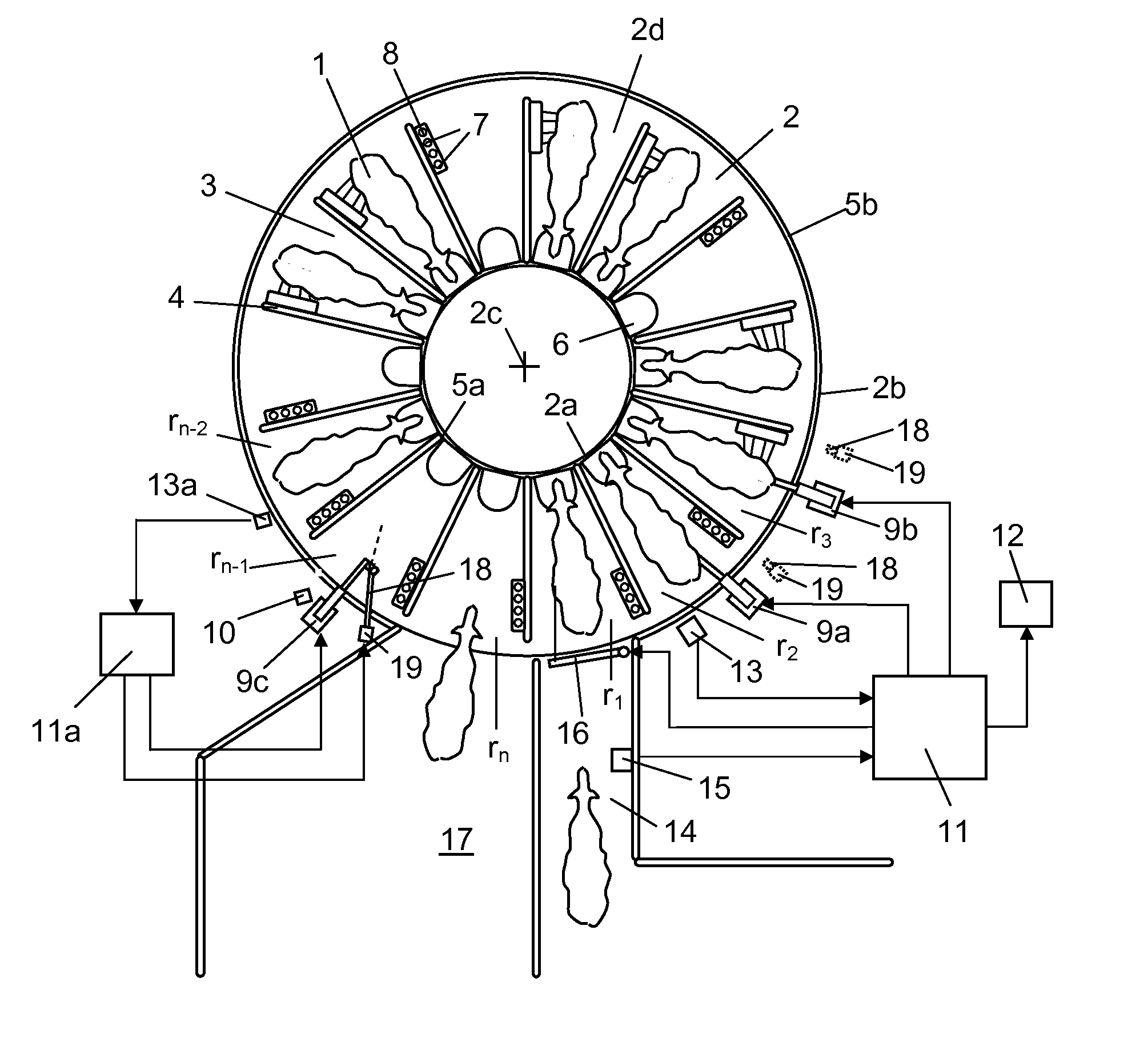
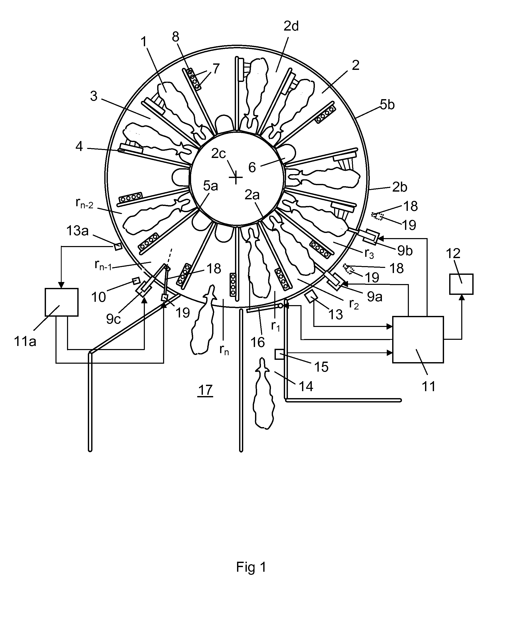
[0025]FIG. 1 shows a rotary parlour for milking of cows 1. The rotary parlour comprises an annular platform 2 having an inner edge portion 2a and an outer edge portion 2b. The platform 2 rotates during operation around a vertical axis 2c. The platform 2 has an upper surface forming a floor surface 2d. A plurality of fence arrangements 4 are arranged on the platform 2. The fence arrangements 4 form milking stall 3 for receiving individual cows 1 in predetermined milking positions. In this case, the fence arrangements 4 have an essentially straight radial extension on the platform 2 between an inner end located at the vicinity of the inner edge portion 2a of the platform and an outer end located at the vicinity of the outer edge portion 2b of the platform. The fence arrangements 4 are arranged at equal intervals around the annular platform 2. An inner fence arrangement 5a is mounted around a main part of the inner periphery of the platform 2. An outer fence arrangement 5b is mounted a...


PUM


Abstract

An apparatus and method for cleaning milking stalls on a platform of a rotary parlour. The rotary parlour includes a robotic manipulation device configured to perform a primary task; a holding device configured to hold the end portion of the hose member in a predetermined parking position, and a control unit. When it is time to clean a milking stall on the platform, the control unit activates the robotic manipulation device such that, instead of performing a primary task, the robotic manipulation device performs an additional task in which the robotic manipulation device grips the end portion of a hose member and moves the end portion from a parking position to a number of cleaning positions from which liquid jets are sprayed from the outlet opening of the end portion against predetermined surfaces to be cleaned in the milking stall.

Description

THE BACKGROUND OF THE INVENTION AND PRIOR ART[0001]The present invention relates to an apparatus and a method for cleaning milking stalls on a platform of a rotary parlour, wherein the rotary parlour comprises a robotic manipulation device configured to perform a primary task in the milking stalls, and wherein the apparatus comprises a hose member having an end portion with an outlet opening and liquid regulating means by which it is possible to regulate the liquid supply to the end portion of the hose member.[0002]In a conventional rotary parlour, the cows walk on to an annular rotating platform and enter a milking stall. In a partly automatic rotary parlour, a milking robot located on the outside or on the inside of the annular platform attaches teat cups to the teats of the cows. The platform usually rotates with a constant low speed. The milking processes of the cows are finished and the cows leave the milking stalls before they have rotated one full revolution on the platform. ...

Claims


Application Information

Patent Timeline
Patent Type & Authority Applications(United States)
IPC IPC(8): A01J7/02A01K1/12
CPCA01J7/022Y10S901/43A01K1/126
Inventor NILSSON, MATS
Owner DELAVAL HLDG AB
Why Eureka
Try Eureka