Methods for recovering waste energy from bleed air ducts

a waste energy and bleed air technology, applied in the manufacture/treatment of thermoelectric devices, energy-efficient board measures, transportation and packaging, etc., can solve the problems of large fuel consumption and the inability to productively use a portion of the initial heat energy in the bleed air

Active Publication Date: 2015-02-19
UNKNOWN
View PDF6 Cites 27 Cited by
  • Summary
  • Abstract
  • Description
  • Claims
  • Application Information

AI Technical Summary

Benefits of technology

[0007]The embodiments provide a method for generation of supplemental electrical power from waste heat in bleed air ducting of an aircraft by coupling an energy conversion device at a hot interface to a bleed air duct and coupling the energy conversion device at a cold interface to an ambient temperature sink. Electrical power is generated with the energy conversion device through use of a thermal gradient between the bleed air duct and ambient temperature sink. The electrical power is then distributed through a power feeder in an aircraft

Problems solved by technology

These generators extract horsepower from the engine shaft and thus contribute to greater fuel consumption.
At least a portion of the initial heat energy in the bleed air is therefore not productively employed.

Method used


Image

  • Methods for recovering waste energy from bleed air ducts
  • Methods for recovering waste energy from bleed air ducts
  • Methods for recovering waste energy from bleed air ducts

Examples


first embodiment

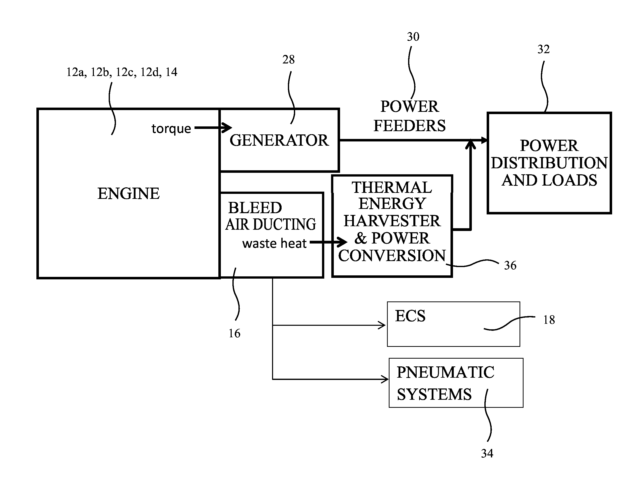
[0027]the thermal energy harvester and power conversion system is shown in FIG. 3. The thermal energy conversion device is a thermoelectric generator (TEG) 38 is mounted to bleed air duct 16 as will be described in greater detail subsequently. A convective heat exchanger 40 extends from a cold side interface of the TEG into the inner volume 42 of the leading edge section. Ambient conditions inside the inner volume 42 may vary from a sea level standard day temperature of 40-80° F. to −21° F. at operating altitude. Temperature differential between the hot side interface and cold side interface of the TEG may therefore range from approximately 220-1020° F. with typical initial bleed air temperatures of 300-380° F.

[0028]An exemplary implementation of the embodiment of FIG. 3 is shown in FIGS. 4, 5A and 5B. As seen in FIG. 4 multiple generator segments 44 are interconnected to form an encircling ring 46 which engages the bleed air duct 16. As shown in FIGS. 5A and 5B, each generator segm...

third embodiment

[0031]the thermal energy harvester and power conversion system is shown in FIG. 7 in which a pulsed heat pipe 72 is coiled on the bleed air duct 16 with a cold interface termination 74 and a hot interface termination 76 operably attached to a Rankine engine 78 as the thermal energy conversion device. The Rankine engine 78 may employ ambient conditions within the leading edge volume 42 or secondary connection to the wing skin 26 or alternative structure for the cold sink for a condenser for operation as known to those skilled in the art. An example Rankine engine for implementation in the described embodiments would be comparable to the Green Machine 4000 series of products by ElectraTherm, 4750 Turbo Circle, Reno, Nev. 89502, Electrical current generate by the Rankine engine 78 is then routed to the power feeders 30 as previously described.

fourth embodiment

[0032]FIG. 8 shows the thermal energy harvester and power conversion system also employing a Rankine engine 78. A fluid heat transfer conduit 80 is coiled on the bleed air duct 16 with a cold interface termination 82 and a hot interface termination 84 operably attached to a Rankine engine 78. A pump 86 circulates the fluid in the fluid heat transfer conduit 80. The Rankine engine 78 may employ ambient conditions within the leading edge volume 42 or secondary connection to the wing skin 26 or alternative structure for the cold sink for operation as known to those skilled in the artElectrical current generate by the Rankine engine 78 is then routed to the power feeders 30 as previously described.

[0033]In either of the third or fourth embodiments, the Rankine engine may be replaced with a Sterling engine with a regenerator acting as the cold interface.


PUM


Abstract

A thermal energy harvester and power conversion system employs a bleed air duct containing the flow of high temperature air from an engine. A lower temperature air source is included with an energy conversion device having a hot interface operably engaged to the bleed air duct and a cold interface operably engaged to the lower temperature air source. The energy conversion device generates electrical power from a thermal gradient between the bleed air duct and the lower temperature air source and the electrical power is routed to a power feeder.

Description

BACKGROUND INFORMATION[0001]1. Field[0002]Embodiments of the disclosure relate generally to the field of electrical energy generation and more particularly to a thermoelectric generators (TEG) or heat pipes in combination with a heat engine to employ bleed air duct temperature differential with local ambient for electrical power generation to be reintroduced into an aircraft electrical power system.[0003]2. Background[0004]Commercial aircraft employ shaft power from main propulsion engines and / or auxiliary power units (APU) (referred to jointly herein as engines) to provide electrical power using electric generators. These generators extract horsepower from the engine shaft and thus contribute to greater fuel consumption. The engines also provide bleed air air for environmental control systems (ECS) and pneumatic systems operation. Bleed air typically is routed from the engine to the ECS or pneumatic systems through a bleed air duct. Temperature of bleed air in the duct may range fr...

Claims


Application Information

Patent Timeline
Patent Type & Authority Applications(United States)
IPC IPC(8): H01L35/28
CPCH01L35/28B64D41/00B64D2013/0618B64D13/00Y02T50/50Y02T50/40H10N10/10
Inventor MITCHELL, BRADLEY J.LAIB, TREVOR M.IYA, SRIDHAR K.ROE, GEORGE M.
Owner UNKNOWN
Why Eureka
Try Eureka