
Stabiliser bar for vehicle cab

a technology for stabilising bars and cabs, which is applied to torsion springs, roofs, washing machines, etc., can solve the problems of affecting the suspension of the cab, affecting the stability of the cab, and affecting the cab's performance, so as to reduce the tendency of pitching in the vehicle, reduce or eliminate the friction, and reduce the storage cost

Inactive Publication Date: 2015-02-19
SCANIA CV AB
View PDF1 Cites 4 Cited by
  • Summary
  • Abstract
  • Description
  • Claims
  • Application Information

AI Technical Summary

Benefits of technology

The invention aims to create a structure that allows for a smoother and more comfortable ride in a vehicle's cab. This is achieved by reducing the rigidity of the structure, which results in less friction between component parts. This results in a higher degree of lateral rigidity, which counteracts lateral movements in the vehicle's cab, while also providing a more or less friction-free suspension in a vertical direction. This solution also reduces wear between component parts, reducing the risk of corrosion and associated rattling.

Problems solved by technology

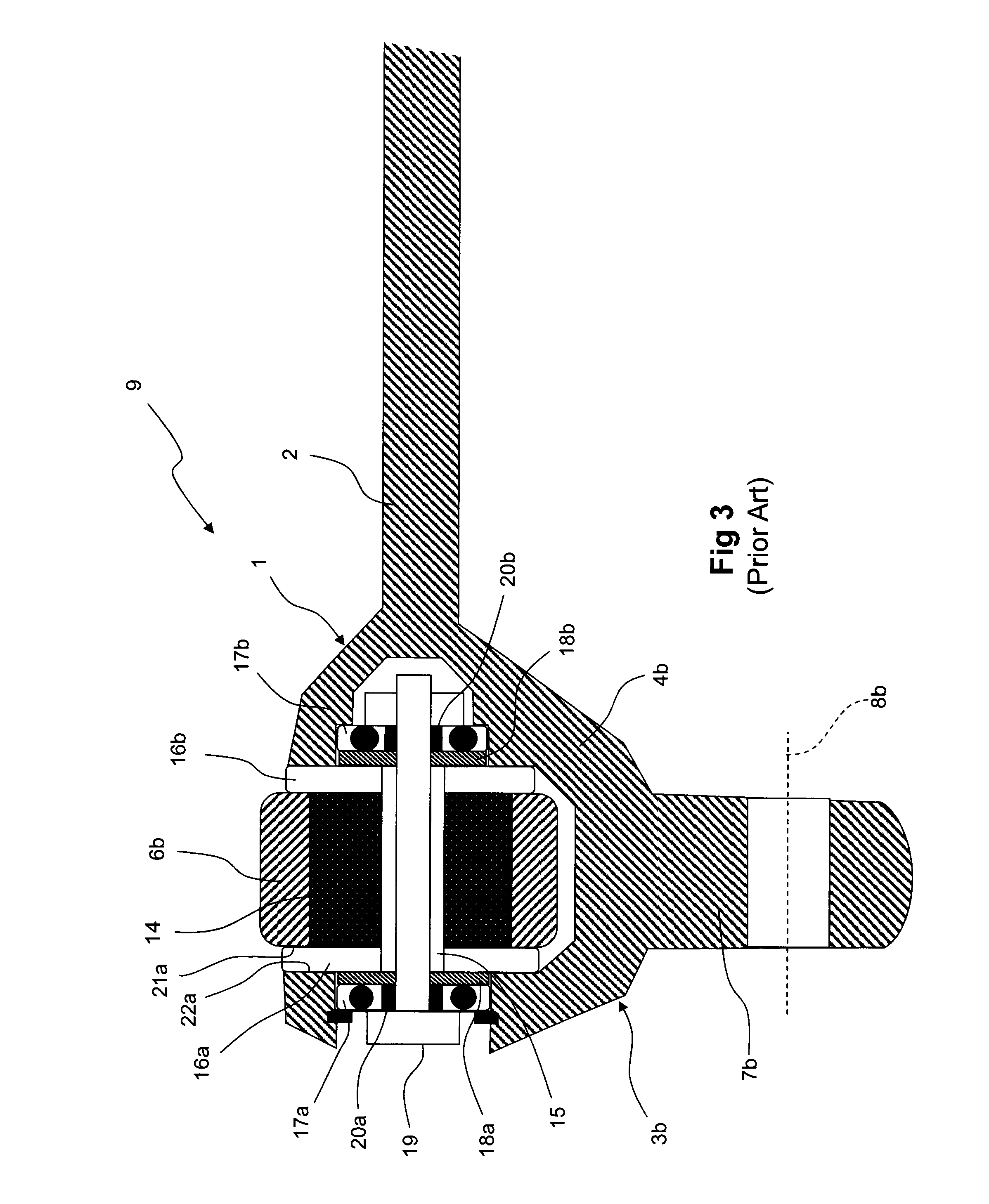
As there is a risk that the bearings, due to their rigid structure, may transfer undesirable vibrations from the vehicle's base to the cab and that this may disturb the driver, a bushing of an elastic material is used in the articulation point, for example a rubber bushing.
The stabiliser bar rotates or pivots in the event of suspension movements in the vehicle / cab and when the cap is tipped to provide access to the engine, and this generates a relative movement between the lateral stops and the stabiliser bar's adjoining supporting surfaces, as the lateral stops are essentially rotationally constant with the chassis fixing, which causes an undesirable friction in these surfaces.
This also results in a rotational rigidity and friction in the articulation point which impairs the cab's suspension.
Other disadvantages are also associated with known solutions.
For example, wear occurs between parts which rotate / pivot or grind against each other, which in turn subsequently wears away the surface from component parts, which may result in corrosion over time.
This in turn causes rattling in the event of the cab's suspension movements which is reproduced in the structure.

Method used


Image

  • Stabiliser bar for vehicle cab
  • Stabiliser bar for vehicle cab
  • Stabiliser bar for vehicle cab

Examples


Embodiment Construction

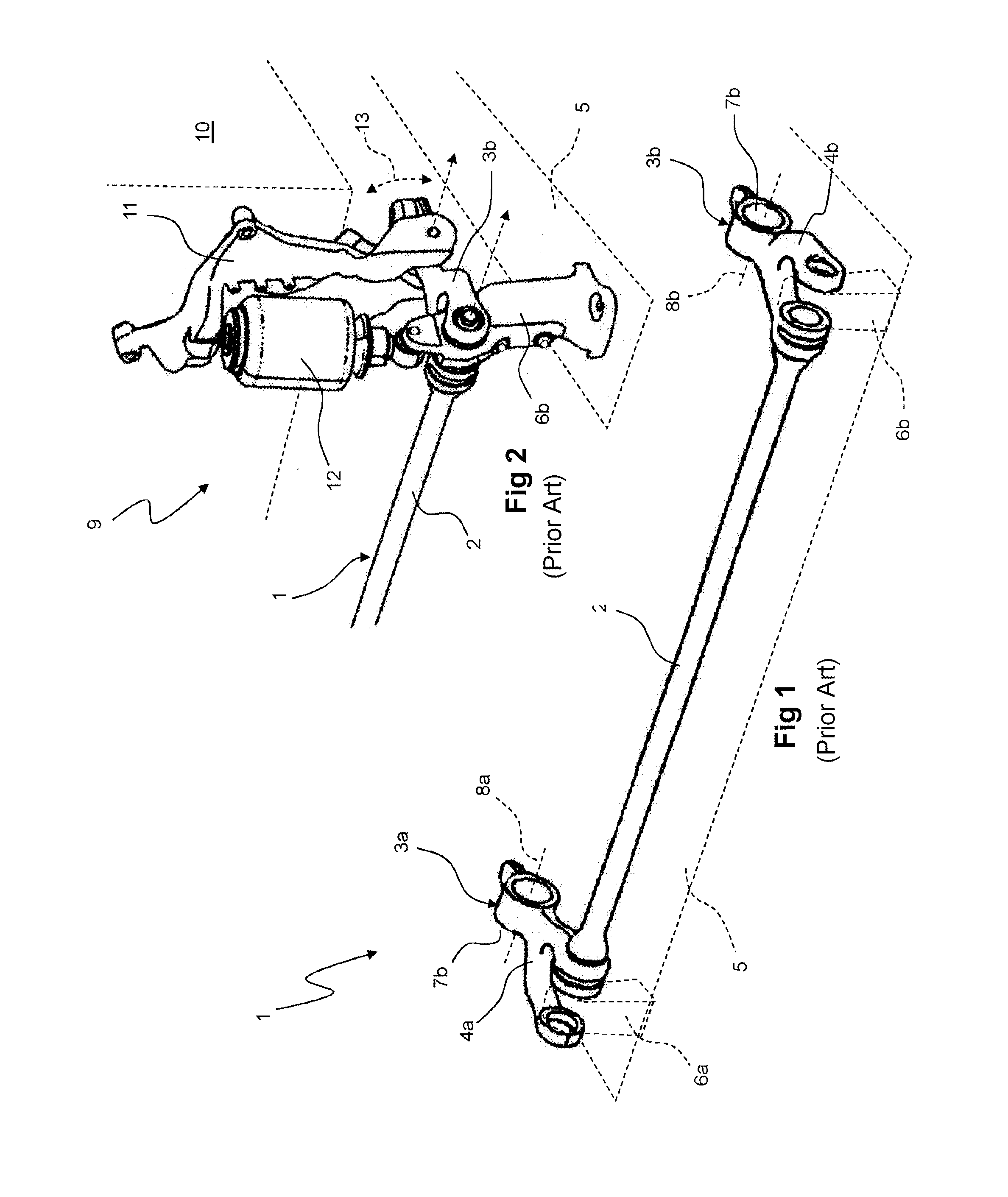
[0032]The invention thus relates to a stabiliser bar for reducing pitching movements in a resiliently suspended vehicle cab. The stabiliser bar is pivotably arranged between two articulation points in the cab, transverse to the longitudinal direction of the vehicle, and compensates for vertical movements which occur when the vehicle moves over an uneven surface with the object of enhancing driver comfort.

[0033]FIG. 1 depicts a perspective view as seen obliquely from in front of a typical stabiliser bar 1 with a pivotable axle 2 arranged between two end section 3a, b, each equipped with a link arm 4a, b. Both end sections 3a, b of the pivotable axle 2 are rotatably supported in a conventional manner in the vehicle's chassis 5 with the aid of chassis fixings 6a, b (schematically illustrated with dotted lines only). The outer rear sections or legs 7a, b of the link arms 4a, b are articulatedly attached to the vehicle cab's frame (not depicted) via articulations 8a, b (illustrated with ...


PUM


Abstract

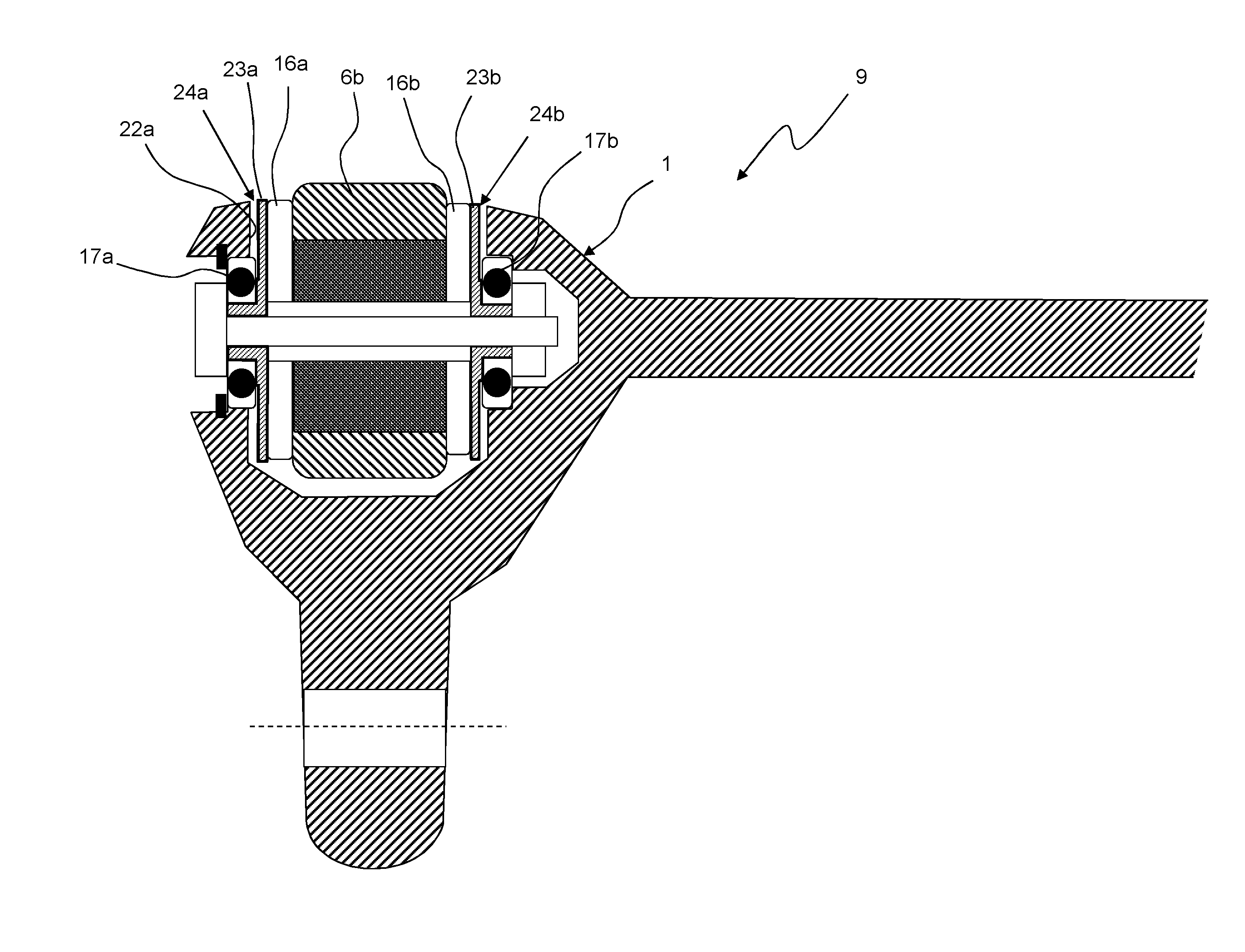
A stabiliser bar (1) to counteract pitching movements in a vehicle cab (10) includes a suspension device (9) with a bushing (14) on each side of which lateral stops (16a, b) are arranged, made from an essentially elastic material, and bearings (17a, b) arranged on the outside of these. A washer-shaped unit (23a, b) is arranged between the bearings (17a, b) and the lateral stops (16a, b) and that unit has a diameter which essentially corresponds to the lateral stops' diameter. The washer-shaped unit (23a, b) is arranged to support the lateral stops (16a, b) in an axial direction and absorb any axial forces exerted by the lateral stops and to form an air gap (24a, b) between the stabiliser bar's supporting surfaces (22a, b) and the washer-shaped unit (23a, b), eliminating direct contact between the stabiliser bar's supporting surfaces (22a, b) and the lateral stops (16a, b).

Description

TECHNICAL FIELD[0001]The present invention relates generally to a stabiliser bar provided with bushing devices to reduce pitching movements in a vehicle. The invention relates particularly to a stabiliser bar for mounting and application to a device for suspending a driver's cab in a vehicle frame, and is particularly intended for commercial heavy vehicles, such as trucks. The invention relates also to a vehicle equipped with such a stabiliser bar.TECHNICAL BACKGROUND[0002]Heavy vehicles are normally equipped with a cab which is suspended from the vehicle's frame to enhance comfort for drivers and their passenger. The cab is often tippable to enable convenient access to the vehicle's engine and facilitate maintenance and servicing and is commonly tipped forwards in relation to the longitudinal direction of the vehicle via articulation points arranged at the front. The cab is commonly resiliently suspended in the vehicle frame via these articulation points, preferably with the aid of...

Claims


Application Information

Patent Timeline
IPC IPC(8): B60G99/00F16F1/16B62D33/06
CPCB60G99/002F16F1/16B62D33/0604B62D33/067F16B43/00F16C35/073F16F1/3814F16F1/3828B60G21/0551B60G2202/135B60G2202/152B60G2204/1222B60G2204/1224B60G2204/162B60G2204/418B60G2206/427B60G2300/02B60G2300/026F16C2326/20B62D33/10F16F1/14
Inventor JARNSTROM, SUNE
Owner SCANIA CV AB
Learn More