Control method for rectifier of switching converters

Active Publication Date: 2015-02-19
STMICROELECTRONICS INT NV
View PDF20 Cites 30 Cited by
  • Summary
  • Abstract
  • Description
  • Claims
  • Application Information

AI Technical Summary

Benefits of technology

[0025]One aspect of the present disclosure is a control device for a rectifier of a switching converter which avoids the undesired earl

Problems solved by technology

However, the maximum efficiency achievable is limited by the losses in the rectifier

Method used


Image

  • Control method for rectifier of switching converters
  • Control method for rectifier of switching converters
  • Control method for rectifier of switching converters

Examples


Example

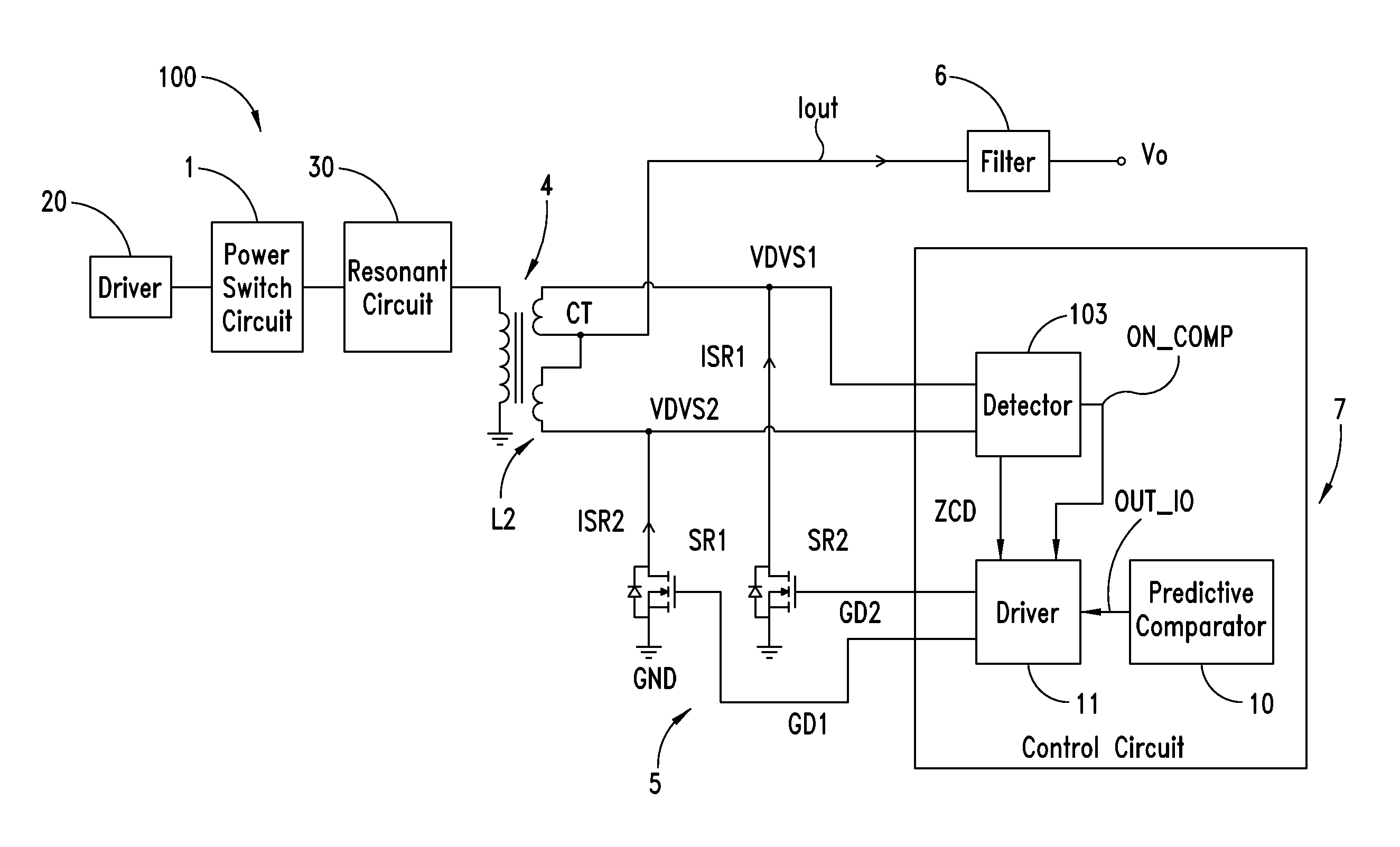
[0051]A control device for a rectifier of a switching converter according to a preferred embodiment of the present disclosure is shown in FIG. 6. The switching converter 100 comprises a power switching circuit block 1, powered by DC voltage and configured to generate a square wave with a certain frequency under the drive given by a first driver 20. For example, the power switching circuit block 1 could be a half-bridge or a full-bridge circuit topology (typically of MOSFET transistors) but other power switching circuit blocks could be equally adopted. The switching converter 100 comprises an impedance 30 connected to the primary winding of a transformer 4; the converter is adapted to provide an output current.

[0052]Preferably the switching converter 100 is an LLC resonant converter and the impedance 30 is a resonant circuit.

[0053]The square wave generated by the power switching circuit block 1 is applied to the resonant circuit 30 tuned to the fundamental frequency of the square wav...


PUM


Abstract

A control device for a transistor of a switching converter rectifier generates a control signal of the transistor and comprises a circuit to measure the conduction time of the body diode of the transistor cycle by cycle. When the conduction time is greater than a first threshold, the off time instant of the transistor is delayed by a first quantity in the next cycles, until the conduction time is less than the first threshold and greater than a second threshold. When the conduction time is between the first and second thresholds, the off time instant is delayed by a fixed second quantity in the next cycles until the conduction time is lower than the second threshold, with the second quantity less than the first quantity. When the conduction time is lower than the second threshold, the off time instant is advanced by the second quantity in the next cycle.

Description

BACKGROUND[0001]1. Technical Field[0002]The present disclosure relates to a control method for rectifier of switching converters.[0003]2. Description of the Related Art[0004]Resonant converters are a large class of forced switching converters characterized by the presence of a half-bridge or a full-bridge circuit topology. In the half-bridge version, for example, the switching elements comprise a high-side transistor and a low-side transistor connected in series between an input voltage and ground. A square wave having a high value corresponding to the power supply voltage and a low value corresponding to ground may be generated by conveniently switching the two transistors.[0005]The square wave generated by the half-bridge is applied to the primary winding of a transformer by means of a resonant circuit which comprises at least one capacitor and one inductor. The secondary winding of the transformer is connected with a rectifier circuit and a filter to provide an output direct volt...

Claims


Application Information

Patent Timeline
IPC IPC(8): H02M7/217H02M3/335H02M1/00
CPCH02M3/33507H02M7/217H02M3/33592Y02B70/10H02M1/0058
Inventor IORIO, ALBERTOSCAPPATURA, GIUSEPPEBIANCO, ALBERTOADRAGNA, CLAUDIODE SIMONE, SILVIOFORESTA, MAURIZIO
Owner STMICROELECTRONICS INT NV
Why Eureka
Try Eureka