Eureka AIR delivers breakthrough ideas for toughest innovation challenges, trusted by R&D personnel around the world.

Micro-gasifier array networking

Active Publication Date: 2015-02-26
V GRID ENERGY SYST INC
View PDF8 Cites 0 Cited by
  • Summary
  • Abstract
  • Description
  • Claims
  • Application Information

AI Technical Summary

Benefits of technology

The patent is about a system that connects multiple micro-gasifier systems using a common gasifier bus or multi-tap pipeline. The system also includes valves to regulate the flow of gas within the system. The technical effect of this invention is to create a more efficient and flexible network of micro-gasifier systems that can operate in a coordinated manner.

Problems solved by technology

Micro-gasifiers were used extensively in Europe during World War II to power internal combustion engine vehicles while conventional gasoline was very difficult to obtain.
However, this is generally regarded as less desirable because positive pressure in the gasifier device can result in highly toxic carbon monoxide gas leakage from various system components such as monitoring ports, biomass feed and ash ports, and various system interconnections.
Restart delay is typically directly proportional to the amount of time the gasifier has been off, with shut down durations of a few minutes resulting in nearly instantaneous restart due to the residual combustible gases retained by the system and the high combustion zone core temperature.
Such a design point is dominated by frictional and accessory losses on the low side and non-optimal combustion dynamics on the high end particularly if the engine designers have pushed the peak output rating of the engine past the optimal combustion operating region.
Likewise, the gasifier is limited by heat losses on the low end which will limit the internal core temperature and, thus, the gasification rate and quality.
At the high end, gasifier system constraints like biomass mass flow, air mass flow, air jetting geometry and hot zone geometry limit the gasifier's performance.
Consequently, the combination of the gasifier and internal combustion engine will typically result in a fairly narrow power range for peak operating efficiency.

Method used


Image

  • Micro-gasifier array networking
  • Micro-gasifier array networking
  • Micro-gasifier array networking

Examples


Embodiment Construction

[0014]In the following paragraphs, embodiments of the present invention will be described in detail by way of example with reference to the attached drawings. Throughout this description, the preferred embodiment and examples shown should be considered as exemplars, rather than as limitations on the present invention. As used herein, the “present invention” refers to any one of the embodiments of the invention described herein, and any equivalents. Furthermore, reference to various feature(s) of the “present invention” throughout this document does not mean that all claimed embodiments or methods must include the referenced feature(s).

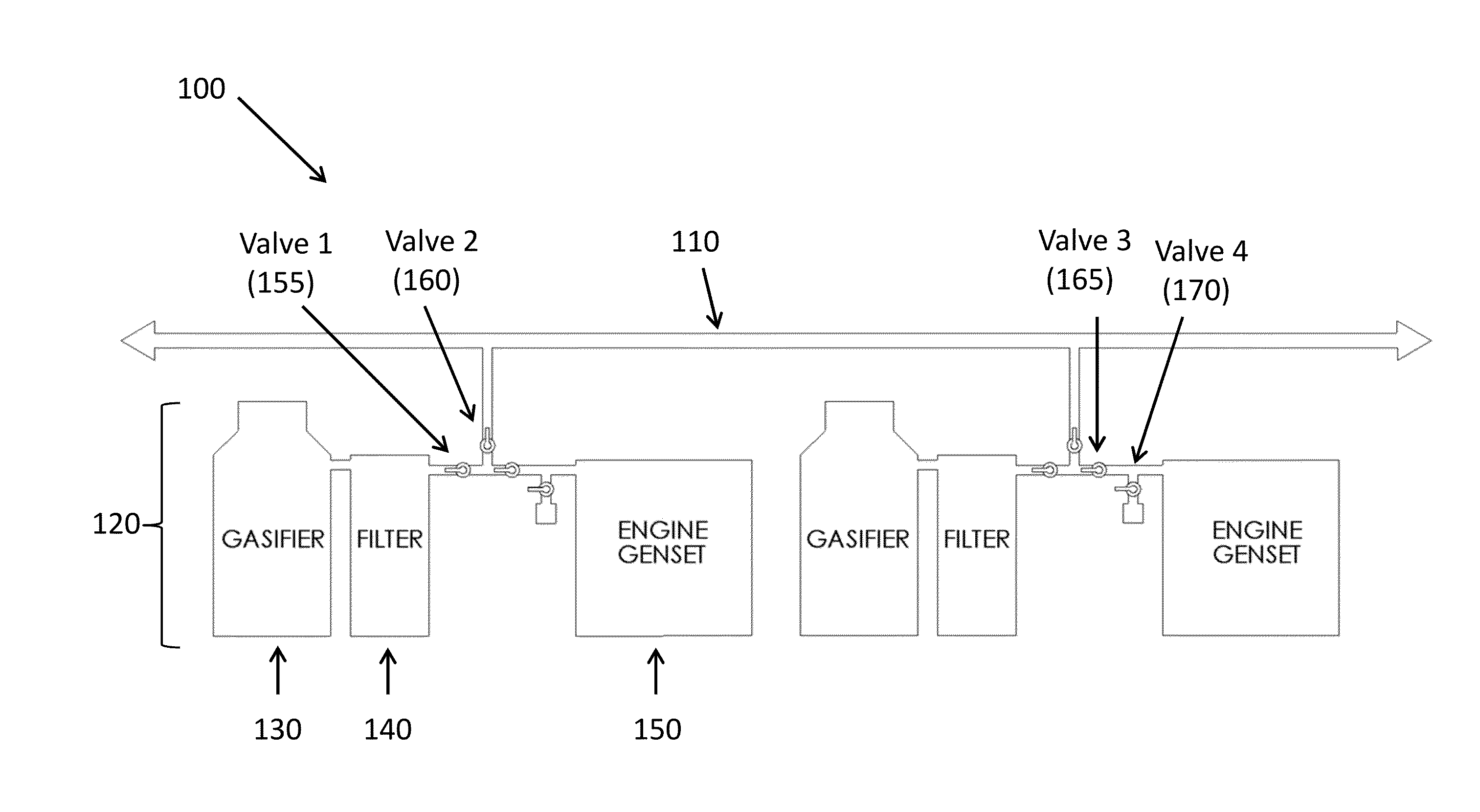
[0015]Embodiments of the invention pertain to the use of two or more micro-gasifier systems in an application where: (i) the demand for shaft power varies widely and rapidly over time, and (ii) biomass conversion efficiency is important such as in an electrical micro-grid.

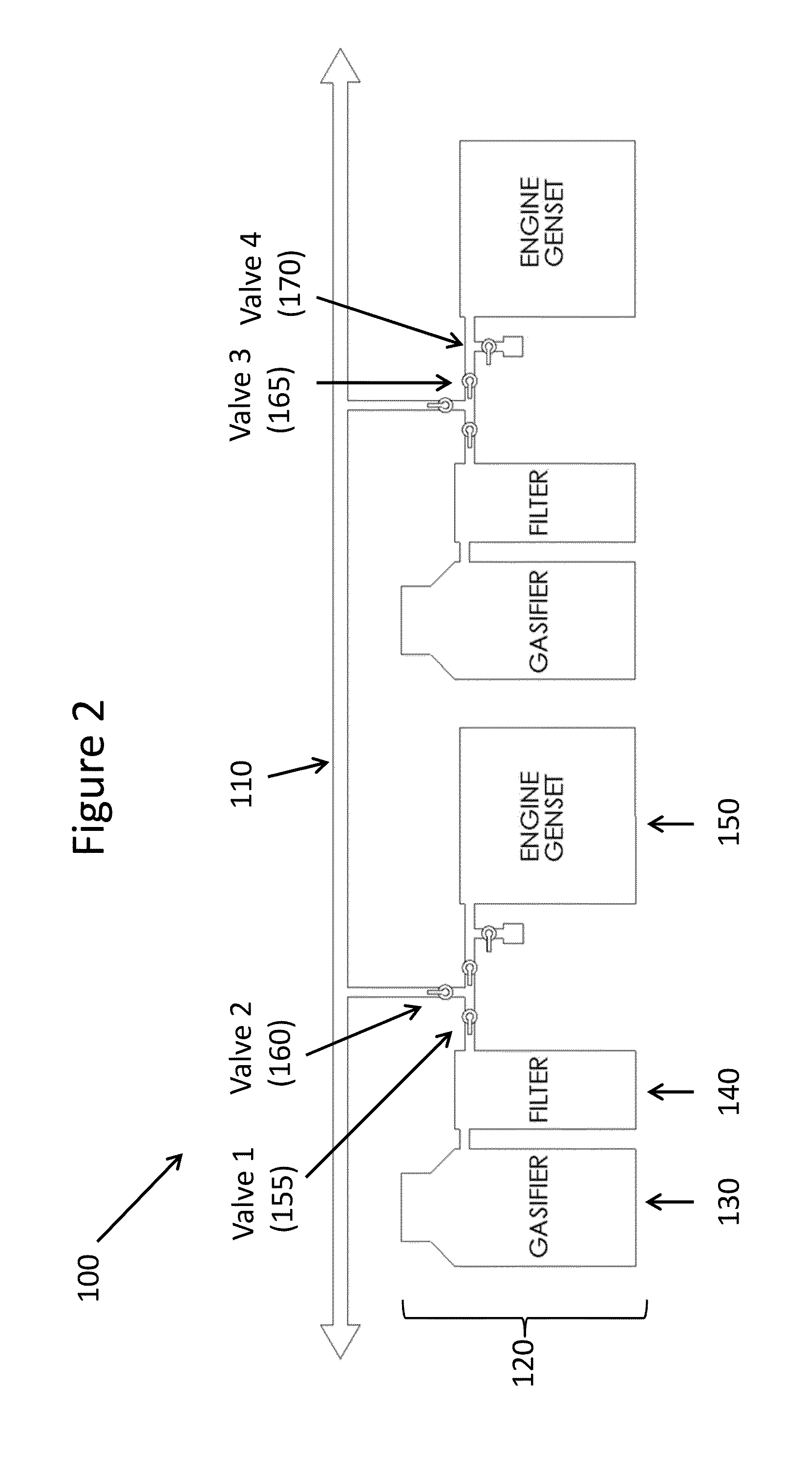
[0016]FIG. 2 illustrates a multi-gasifier array 100 comprising a common gasifier ...


PUM


Abstract

A collection of gasifier fueled engine systems is networked through a system of connecting pipes and valves in order to provide fast response to output power demands and to extend the range of power levels at which the system exhibits high conversion efficiency.

Description

RELATED APPLICATIONS[0001]This application claims priority to U.S. Provisional Patent Application No. 61 / 867,716 filed on Aug. 20, 2013, the content of which is incorporated herein by reference in its entirety.FIELD OF THE INVENTION[0002]The invention broadly relates to micro-gasifier array networking.BACKGROUND OF THE INVENTION[0003]Micro-gasifiers were used extensively in Europe during World War II to power internal combustion engine vehicles while conventional gasoline was very difficult to obtain. The basic operating principles of such devices will now be described. Initially, dry biomass is combusted in an enclosed container under a mild vacuum as generated by the intake manifold of a reciprocating piston engine. Air inlets and gasifier output stream connections are arranged so that the biomass is only partially combusted, resulting in an exhaust stream which contains carbon monoxide and may additionally contain hydrogen and hydrocarbon gasses. This gas can be further combusted...

Claims


Application Information

Patent Timeline
IPC IPC(8): F02B43/08F02B73/00C10J3/72F02D25/00F02D29/06F02M21/08F02B63/04F02D19/04
CPCF02B43/08F02B63/04F02B73/00C10J3/723F02D25/00F02D29/06F02M21/08F02D19/04C10J2200/33C10J3/721C10J2300/1671C10J3/726F02M25/12F02M27/02F02B1/04F02B43/10Y02T10/30
Inventor CHEIKY, MICHAEL
Owner V GRID ENERGY SYST INC
Why Eureka
Eureka Blog
Learn More