
Automated meter reading system, communication and control network from automated meter reading, meter data collector, and associated methods

Inactive Publication Date: 2007-01-18
ENERGY TECH GROUP
View PDF54 Cites 260 Cited by
  • Summary
  • Abstract
  • Description
  • Claims
  • Application Information

AI Technical Summary

Benefits of technology

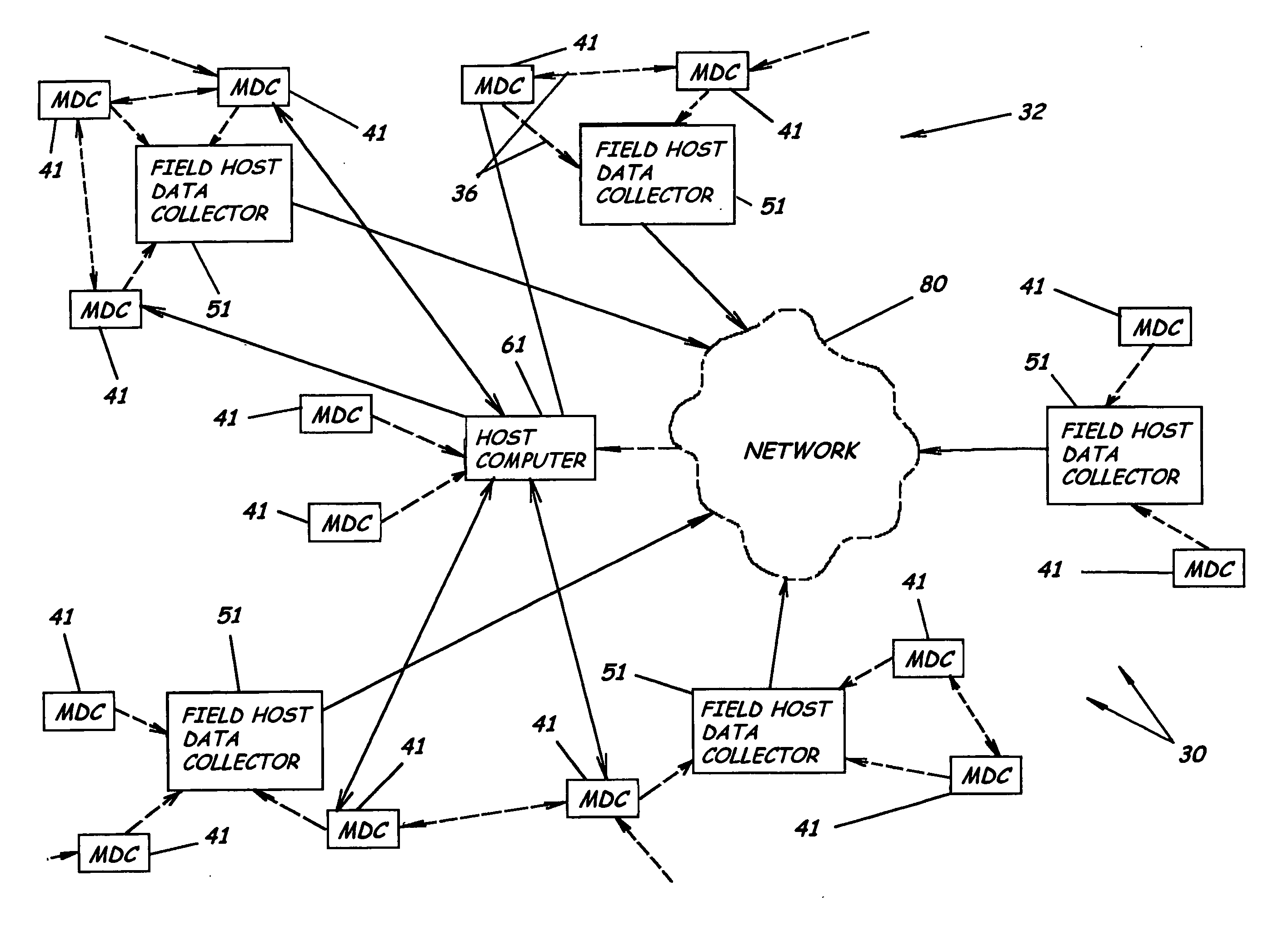
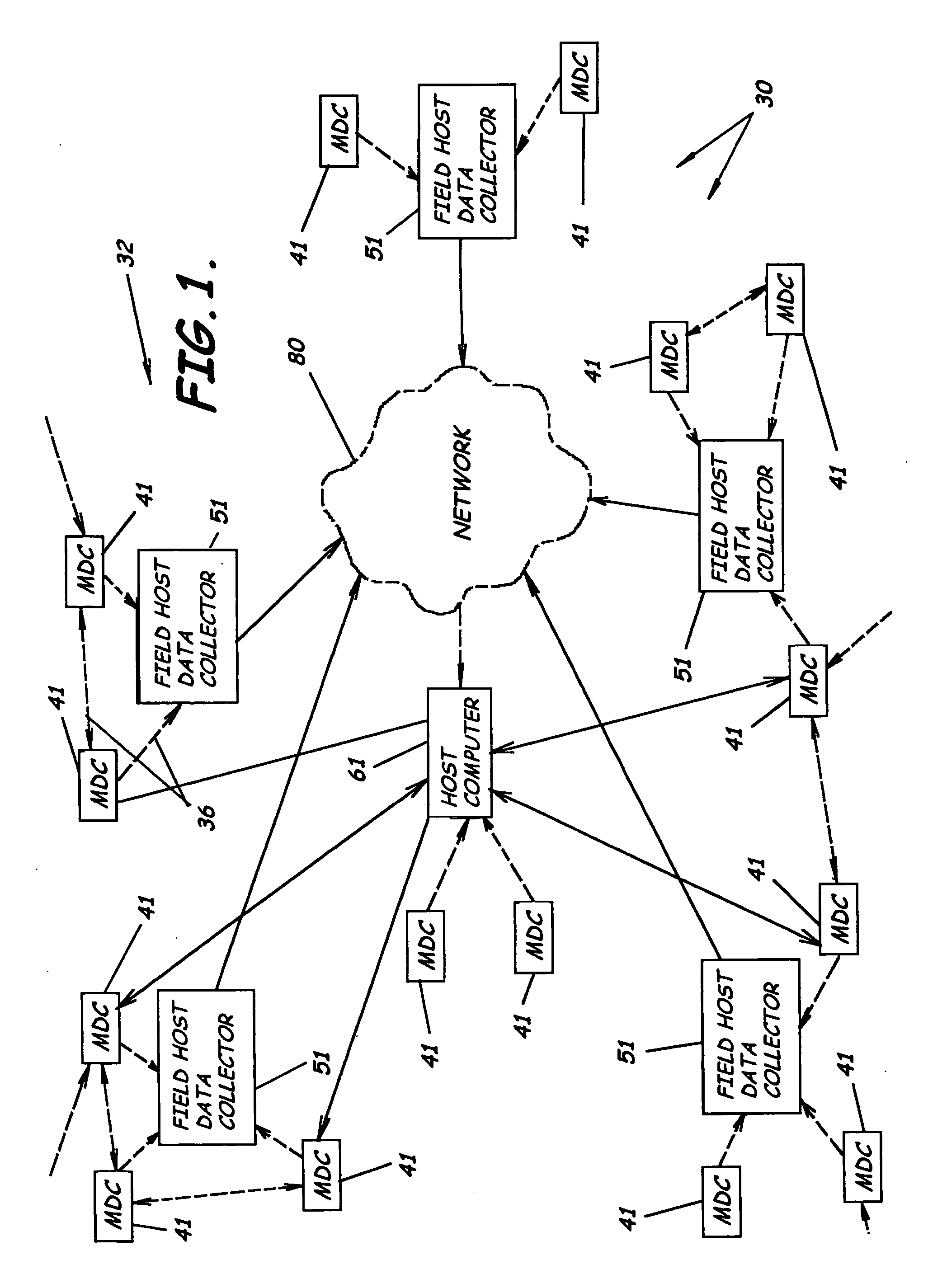
[0016] In view of the foregoing, embodiments of the present invention advantageously provide an automated utility meter reading network system, program product, and methods related to an automated data acquisition and energy management. Embodiments of the present invention provide an automated meter reading network system to automate and transform the process of metering electricity, gas, water, steam, and the like, while reducing costs, adding value, enhancing service, and decreasing time of collection. Embodiments of the present invention advantageously provide a distributed network system to collect and analyze utility usage data that includes sensors interfaced with or connected to utility meters, which provide the ability to take automated utility meter readings, and a remote automated meter reading control center including a host computer, e.g., a server, for gathering and processing the utility usage data. Embodiments of the present invention provide a robust system that, through a refresh process, can continuously analyze individual segments of the mesh network in order to ensure availability of the maximum number of segments. Embodiments of the present invention also provide an automated meter reading network system that supports bi-directional communications with a network of meter data collectors capable of automated reconfiguration of the network structure and automated adjustment of transmission power level settings due to environmental factors.
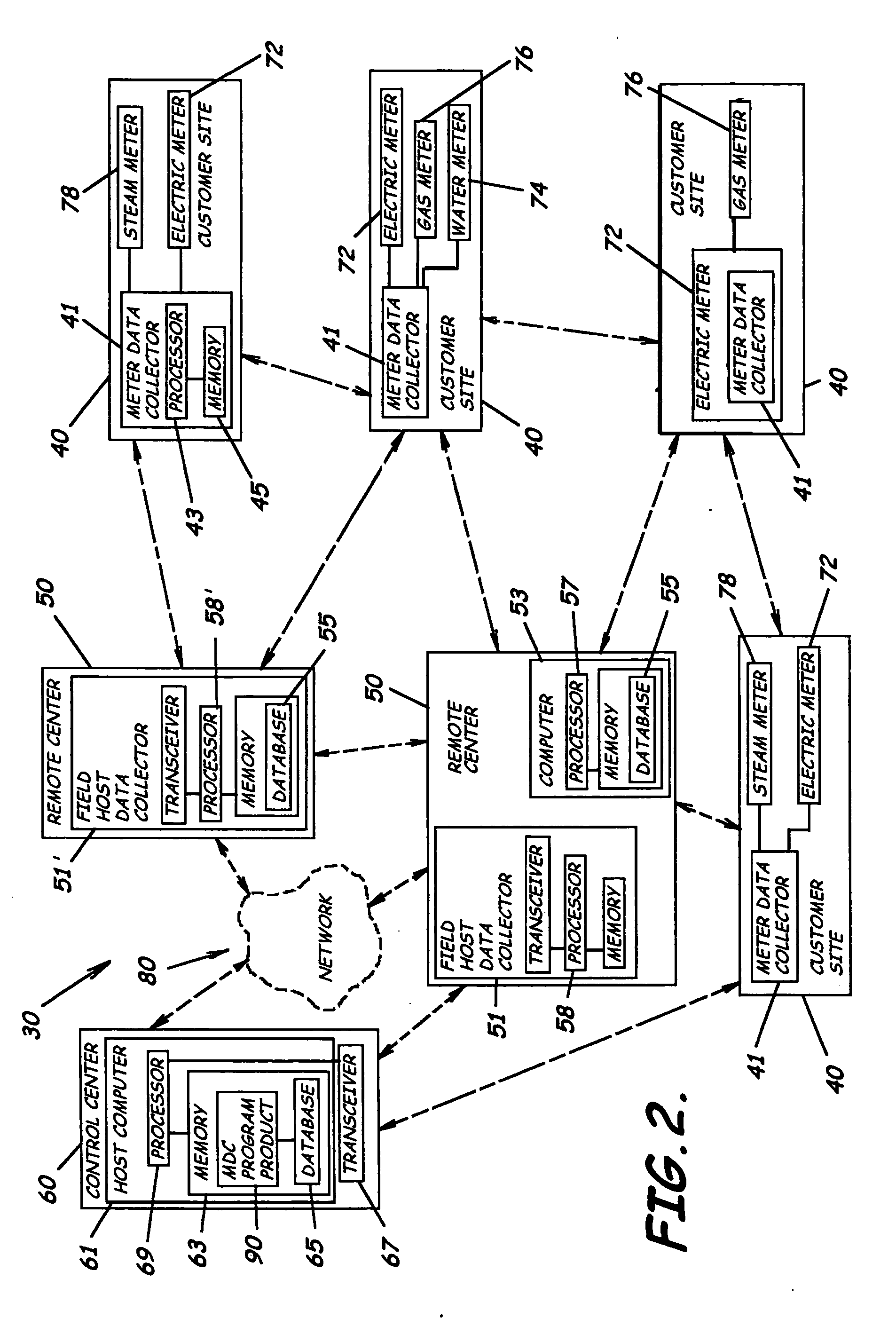
[0017] More specifically, an embodiment of the present invention provides an automated meter reading network system including at least one but preferably a plurality of utility meters, e.g., water, gas, steam, electric, and / or other, some located at the same customer site, others located at separate customer sites. A plurality of sensors are correspondingly each interfaced with and positioned adjacent a separate one of the plurality of utility meters to thereby sense utility usage data from each of the plurality of utility meters. A plurality of meter data collectors are each preferably positioned, for example, within one of the utility meters and / or adjacent one or more of the utility meters, and in communication with one or more of the sensors to collect the utility usage data. Each meter data collector can be configured to collect data from up to 20 or more metering inputs and can provide a digital output board for device control. An analog input module can also be provided to allow for monitoring of customer equipment, providing municipalities the ability to create additional revenue sources. For example, if equipped with the analog input module, each meter data collector can monitor air-conditioning performance points, such as pressure and temperature. All metering data can be date and time stamped, providing an accurate record of the exact day and time the customer's meters are read.

Problems solved by technology

Utility companies and municipalities for many years have been burdened with the labor intensive and cumbersome task of manually collecting meter readings, managing data from the field into the accounting area, and managing the billing and collection of invoices.
This process is costly, is time consuming, and can involve various risks to personnel involved in manually collecting meter data.
The process involves labor, motorized transportation, and numerous employee overhead-related costs.
Manually reading the meters often results in numerous other expenses including those related to human error.
For example, a high bill caused by an incorrect manual read or estimated read often motivates customers to pay later, resulting in increased working capital requirements and corresponding expenses for the utility.
Additionally, the utility has to handle the customer complaints (a call center cost) and may have to read the meter again to verify the error.
As the complaint progresses, the utility faces administrative costs associated with routing and processing the complaint from the call center to the meter department.
An additional cost includes the potential loss of a customer who, even after resolution, feels the process was such an excessive burden as to prompt the customer to switch utility providers.
This approach, however, still requires the manual visit to each meter location and time downloading the data to the billing system.
Also, the data is transferred from the mobile receiver to the database, which again reduces manpower and data handling.
This approach, however, can require a complicated infrastructure to be installed.
Power lines operate as very large antennas and can receive a large amount of noise.
These filters can be very expensive.
Also, the connections often are at line voltage, making it more dangerous and time consuming to install.
Another problem with expanding the use of control systems technology to such distributed systems are the costs associated with the sensor-actuator infrastructure required to monitor and control functions within such systems.
Not only is there the expense associated with developing and installing appropriate sensors and actuators, but there is the added expense of connecting functional sensors and controllers with the local controller and the cost of the local controller.
This methodology is also quite intrusive as the cables must be run to physically interconnect the various nodes in the network.
In addition to the high cost of installation, however, such a system is not useable in areas without access to a cable system.
Moreover, networks that are interconnected with cables are subject to physical disruption of the cables.
These wireless networks, however, have limitations.
For example, because these wireless networks generally have a point-to-point loop configuration, when one node is disabled, the integrity of the entire network can be affected.
Moreover, if the master node of such a network is disabled, the network can become isolated.
Further, such master-slave relationship results in a significant increase in processing overhead in the node controller or CPU.
Building, launching and maintaining a fleet of satellites, however, is very expensive.
Recognized by the Applicant is that if the power is not initially set correctly, the RF transmitter will not function properly within the network configuration.
Further, recognized by the Applicant is that the environment with which the RF transmitters are positioned may change over time such that the RF transmitter at the predetermined power setting will be rendered ineffective.
Additionally, recognized by the Applicant is that networks using such low-power RF transmitters may lose utility usage data due to typically temporary interruptions in the transmission of such usage data when such data is being relayed between multiple low-power RF transmitters.
Although such automated meter reading servers may address some meter data management concerns, these systems still fail to address communication concerns set forth above with respect to collecting billing or usage data and transmitting the data to a control center having such an automated meter reading server.

Method used


Image

  • Automated meter reading system, communication and control network from automated meter reading, meter data collector, and associated methods
  • Automated meter reading system, communication and control network from automated meter reading, meter data collector, and associated methods
  • Automated meter reading system, communication and control network from automated meter reading, meter data collector, and associated methods

Examples


Embodiment Construction

[0065] The present invention will now be described more fully hereinafter with reference to the accompanying drawings, which illustrate embodiments of the invention. This invention may, however, be embodied in many different forms and should not be construed as limited to the illustrated embodiments set forth herein. Rather, these embodiments are provided so that this disclosure will be thorough and complete, and will fully convey the scope of the invention to those skilled in the art. Like numbers refer to like elements throughout. The prime notation, if used, indicates similar elements in alternative embodiments.

[0066] As illustrated in FIGS. 1-21, embodiments of the present invention incorporate an automated meter reading network system 30 including a multifunction meter data collector 41, a utility meter e.g., electric 72, water 74, gas 76, steam 78, or other usage, and an at least one sensor 73, 75, 77, 79, e.g., an encoder or other sensor element known to those skilled in the...


PUM


Abstract

An automated meter reading network system to collect utility usage data from multiple utility meters having utility meter sensors, program product, and associated methods are provided. The system includes multiple meter data collectors each in communication with one or more utility meters to collect utility usage data and forming a wireless communications network. The system also includes a host computer in communication with the meter data collectors either directly or through multiple field host data collectors which can be connected to the host computer through a wide area network. The system also includes a meter data collector program product at least partially stored in the memory of the host computer to manage the communication network. The meter data collector program product is adapted to analyze signal strength between nodes and to dynamically adjust the power level settings of the individual nodes to enhance network performance.

Description

RELATED APPLICATIONS [0001] This application is a continuation-in-part of and claims priority to and the benefit of U.S. patent application Ser. No. 10 / 779,429 filed on Feb. 13, 2004, titled “Automated Meter Reading System, Communication and Control Network for Automated Meter Reading, Meter Data Collector, and Associated Methods,” which claims the benefit of U.S. Provisional Application Ser. No. 60 / 447,815, filed on Feb. 14, 2003, titled “Automated Meter Reading System, Communication and Control Network for Automated Meter Reading, Meter Data Collector, and Associated Methods,” both of which are incorporated herein by reference in their entireties.BACKGROUND OF THE INVENTION [0002] 1. Field of the Invention [0003] The present invention relates in general to the field of utility meters. More particularly, the present invention relates to automatic equipment, systems, networks, and software for remote reading of utility meters. [0004] 2. Description of Related Art [0005] Utility comp...

Claims


Application Information

Patent Timeline
IPC IPC(8): G08C15/06
CPCG01D4/002H04Q9/00H04W40/02Y02B90/241H04Q2209/25Y04S20/32Y04S20/42H04Q2209/60Y02B90/246Y02B90/20Y04S20/30G01D2204/45
Inventor BOAZ, JON A.
Owner ENERGY TECH GROUP
Learn More