
Wiring board structure

a wiring board and structure technology, applied in the field of wiring board structure, can solve the problems of heat dissipation difficulty, heat dissipation space restriction and compression in the said portable electronic device, and achieve the effect of improving the heat dissipation efficiency of the wiring board structur

Inactive Publication Date: 2015-02-26
UNIMICRON TECH CORP
View PDF5 Cites 7 Cited by
  • Summary
  • Abstract
  • Description
  • Claims
  • Application Information

AI Technical Summary

Benefits of technology

The invention is a wiring board with a special cooling system that helps to dissipate heat more effectively. This is achieved by embedding an active cooler in the wiring board or applying a material to fill the conductive vias. When an electric current is conducted through the coolant, it quickly absorbs the heat from the hot surface and releases it through the cold surface. This prevents the heat from accumulating and improves the overall heat dissipation efficiency of the wiring board.

Problems solved by technology

However, since the portable electronic devices such as the tablet computer and the smart phones include a relatively smaller internal space, spaces for heat dissipation in said portable electronic devices are restricted and compressed.
Designs toward extremely compressed space results in difficulties for heat dissipation.
Further, problems regarding heat dissipation encountered by the portable electronic devices are also related to complexity of the devices.
Circuit design for smart electronic devices with multiple functions is relatively more complex, which also influences in design for high efficiency heat dissipation.
As a result, this not only results in discomfort for the users in use, but also possibly leads to damages on the chips.

Method used


Image

  • Wiring board structure
  • Wiring board structure
  • Wiring board structure

Examples


Embodiment Construction

[0018]Reference will now be made in detail to the present preferred embodiments of the invention, examples of which are illustrated in the accompanying drawings. Wherever possible, the same reference numbers are used in the drawings and the description to refer to the same or like parts.

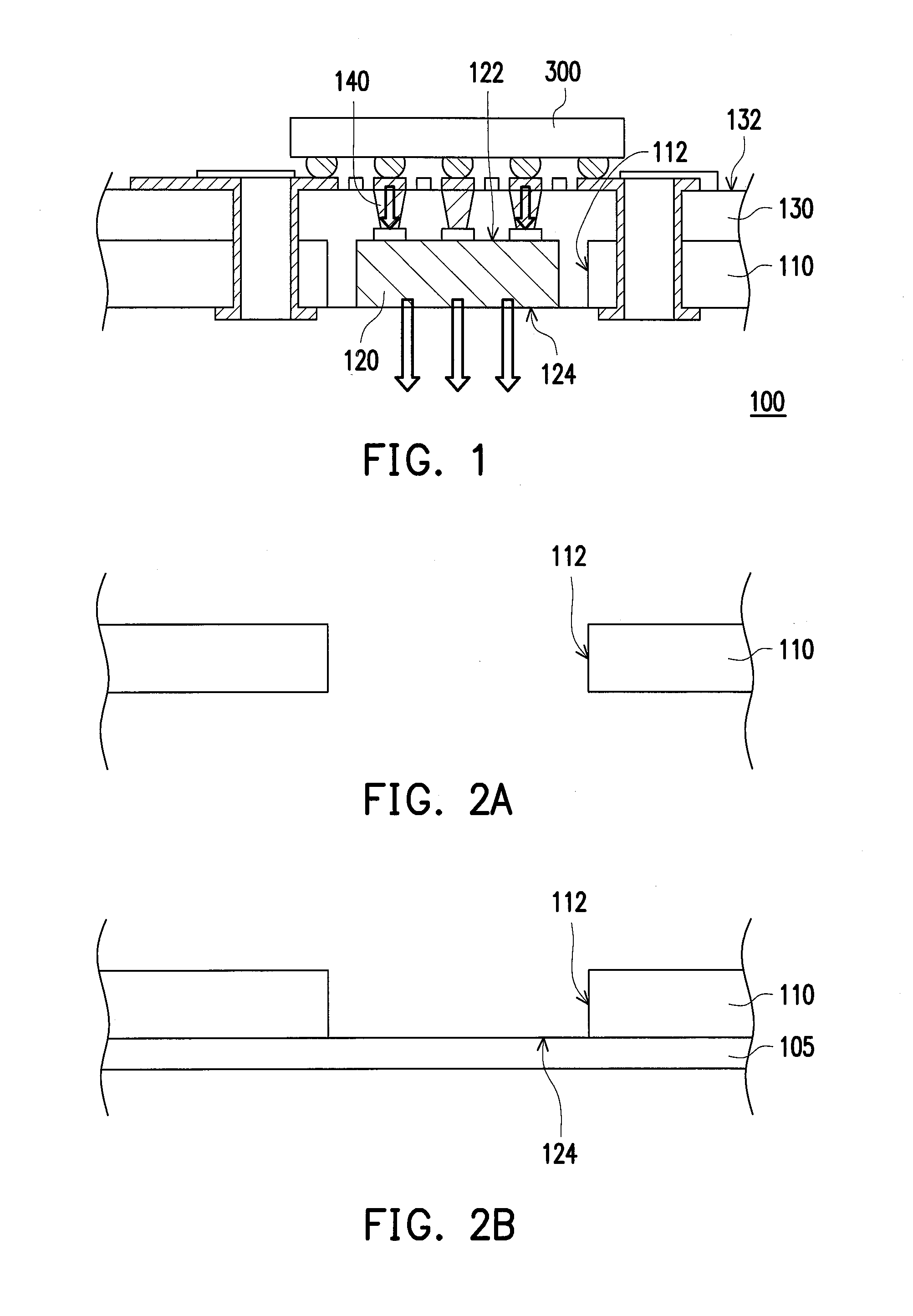
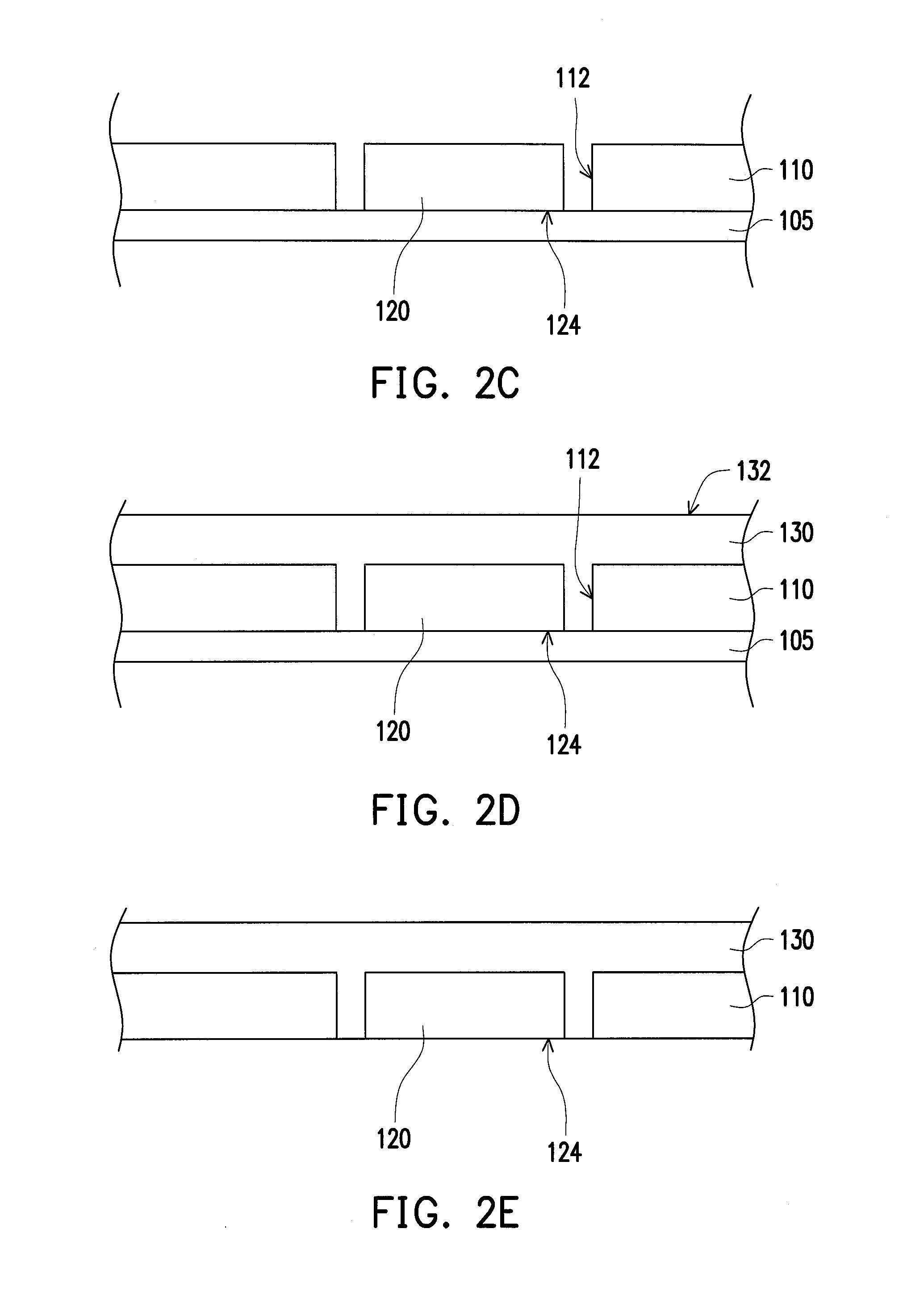
[0019]FIG. 1 is a schematic view of a wiring board structure according to an embodiment of the invention. Referring to FIG. 1, a wiring board structure 100 is adapted to carry a heat-generating component 300. The wiring board structure 100 includes a core layer 110, an active cooler 120, a first dielectric layer 130 and a plurality of first conductive vias 140. The core layer 110 has a cavity 112 penetrating the core layer 110. The active cooler 120 is disposed in the cavity 112, and includes a cold surface 122 and a hot surface 124, in which heat of the heat-generating component 300 can absorbed through the cold surface 122, and the absorbed heat can be radiated through the hot surface 124. In the p...


PUM


Abstract

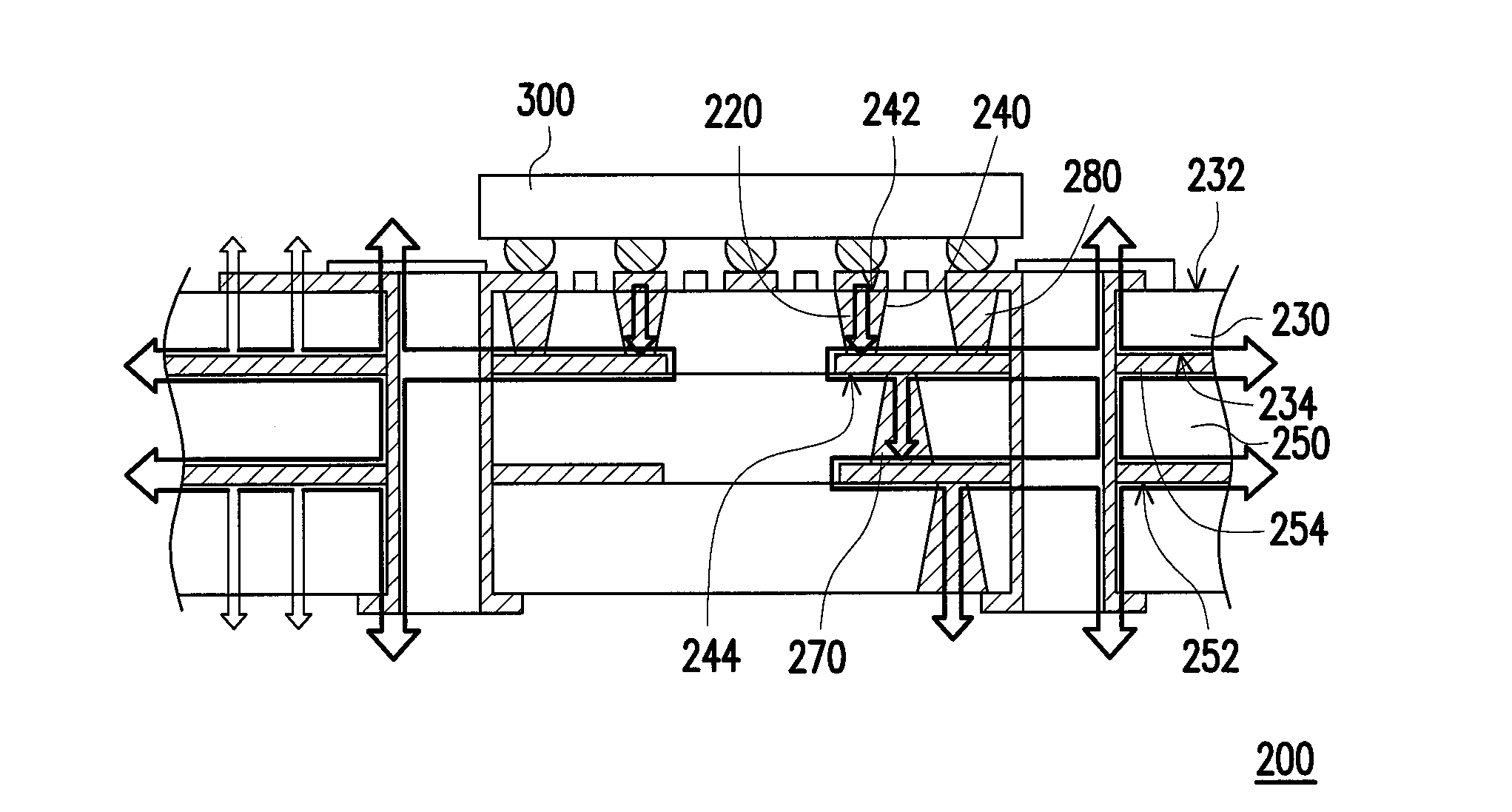
A wiring board structure adapted to carry a heat generating component is provided. The wiring board structure includes a core layer, an active cooler, a dielectric layer and a plurality of conductive vias. The core layer has a cavity penetrating through the core layer. The active cooler includes a cold surface and a hot surface. The active cooler is disposed in the cavity. The dielectric layer covers the core layer and fills a gap between the active cooler and the cavity. The heat-generating component is disposed on an outer surface of the dielectric layer. The conductive vias are disposed in the dielectric layer and connecting the cold surface and the outer surface to connect the heat-generating component and the active cooler. A wiring board structure having an active cooling via is also provided.

Description

CROSS-REFERENCE TO RELATED APPLICATION[0001]This application claims the priority benefit of Taiwan application serial no. 102130006, filed on Aug. 22, 2013. The entirety of the above-mentioned patent application is hereby incorporated by reference herein and made a part of this specification.BACKGROUND OF THE INVENTION[0002]1. Field of the Invention[0003]The invention relates to a wiring board structure, and more particularly to a wiring board structure having more preferable heat dissipation efficiency.[0004]2. Description of Related Art[0005]Advancement of technology leads to continuous development of portable electronic devices towards compactness and capabilities for performing multiple functions. For instance, tablet computers or smart phones with compact-sized and low-profiled appearances are suitable for users to carry and operate. Accordingly, the more powerful electronic devices require chips of higher speed. However, as the chips with higher speed generate more heat, and t...

Claims


Application Information

Patent Timeline
Patent Type & Authority Applications(United States)
IPC IPC(8): H05K1/02
CPCH05K2201/06H05K1/0206H05K1/0203H05K1/0207H05K1/16H05K1/185H05K3/4602H05K2201/0187H05K2201/0195H05K2201/09527H05K2201/10219H01L2224/16225H01L2224/04105H01L2224/12105H01L2224/16227H01L24/19H01L2224/73259H01L21/568H01L2224/18
Inventor WU, MING-HAOCHENG, WEI-MINGCHANG, HUNG-LIN
Owner UNIMICRON TECH CORP
Learn More