
Brake Disc Arrangement for Disc Brakes

a technology of brake discs and brake discs, which is applied in the direction of brake discs, manufacturing tools, mechanical equipment, etc., can solve the problems of increasing manufacturing costs and difficult control, and achieve the effect of good corrosion resistance and high degree of deformation

Inactive Publication Date: 2015-02-26
SAF HOLLAND GMBH
View PDF30 Cites 7 Cited by
  • Summary
  • Abstract
  • Description
  • Claims
  • Application Information

AI Technical Summary

Benefits of technology

The patent text describes a connecting element that can be used in a friction ring or adapter to adjust the fit and friction of a braking system. The connecting element is designed with a cylindrical hollow body and a closed side. It can be bevelled or chamfered to fit optimally into the contour without damaging it. The open side of the connecting element can be adjusted for different tools or operative media. The connecting element can be moved axially along the braking system and has different wall thicknesses along its length to accommodate different inner geometries of the braking system. It can also be coated to make its movement easier or to influence its fit and friction. The technical effect of this design is to improve the performance and reliability of braking systems.

Problems solved by technology

Due to the complex manufacturing process, however, finishing work on such brake disc arrangements is necessary, wherein there is the danger that this causes notches, which are in critical regions.
Additionally, this process step increases the manufacturing costs.
Furthermore, such brake disc arrangements are limited to manufacturing processes by casting, which due to the complexity of the component and its safety-relevant properties are very difficult to control.

Method used


Image

  • Brake Disc Arrangement for Disc Brakes
  • Brake Disc Arrangement for Disc Brakes
  • Brake Disc Arrangement for Disc Brakes

Examples


Embodiment Construction

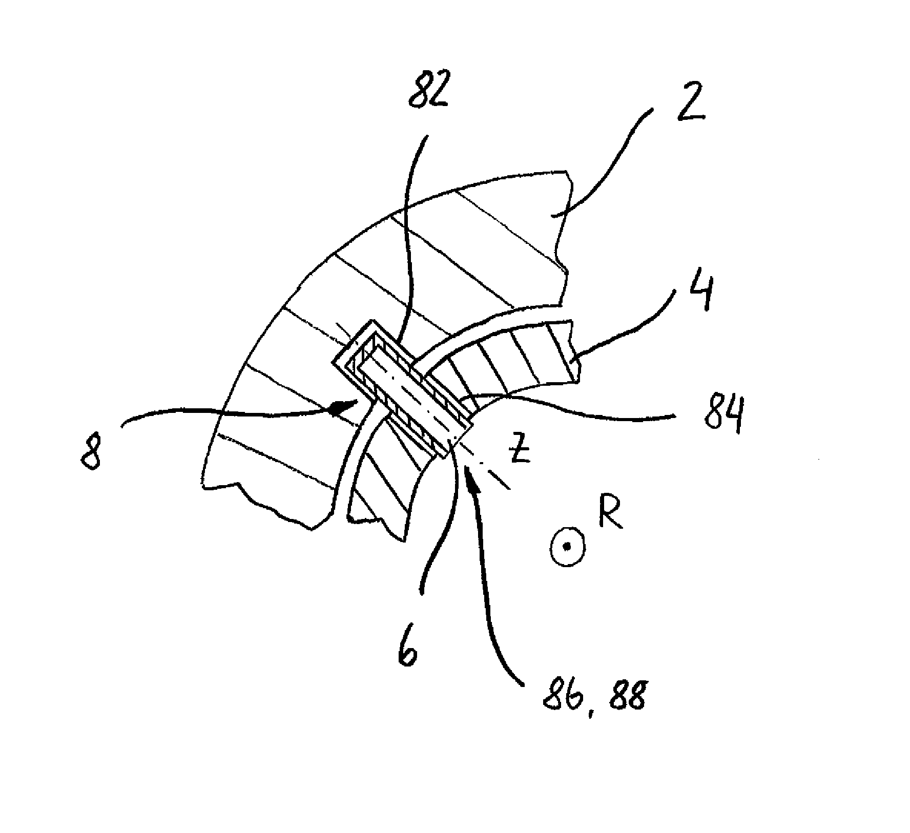
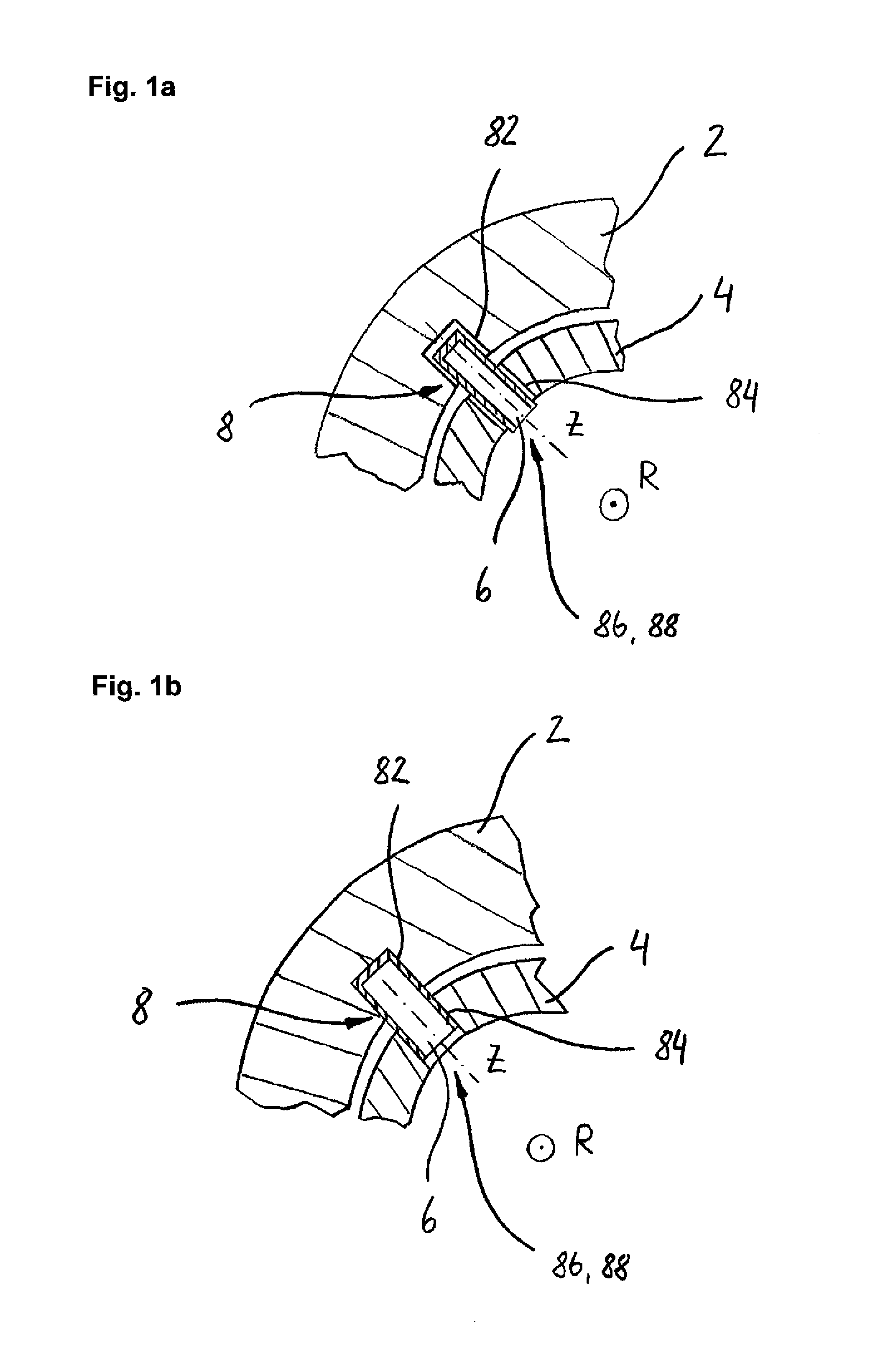
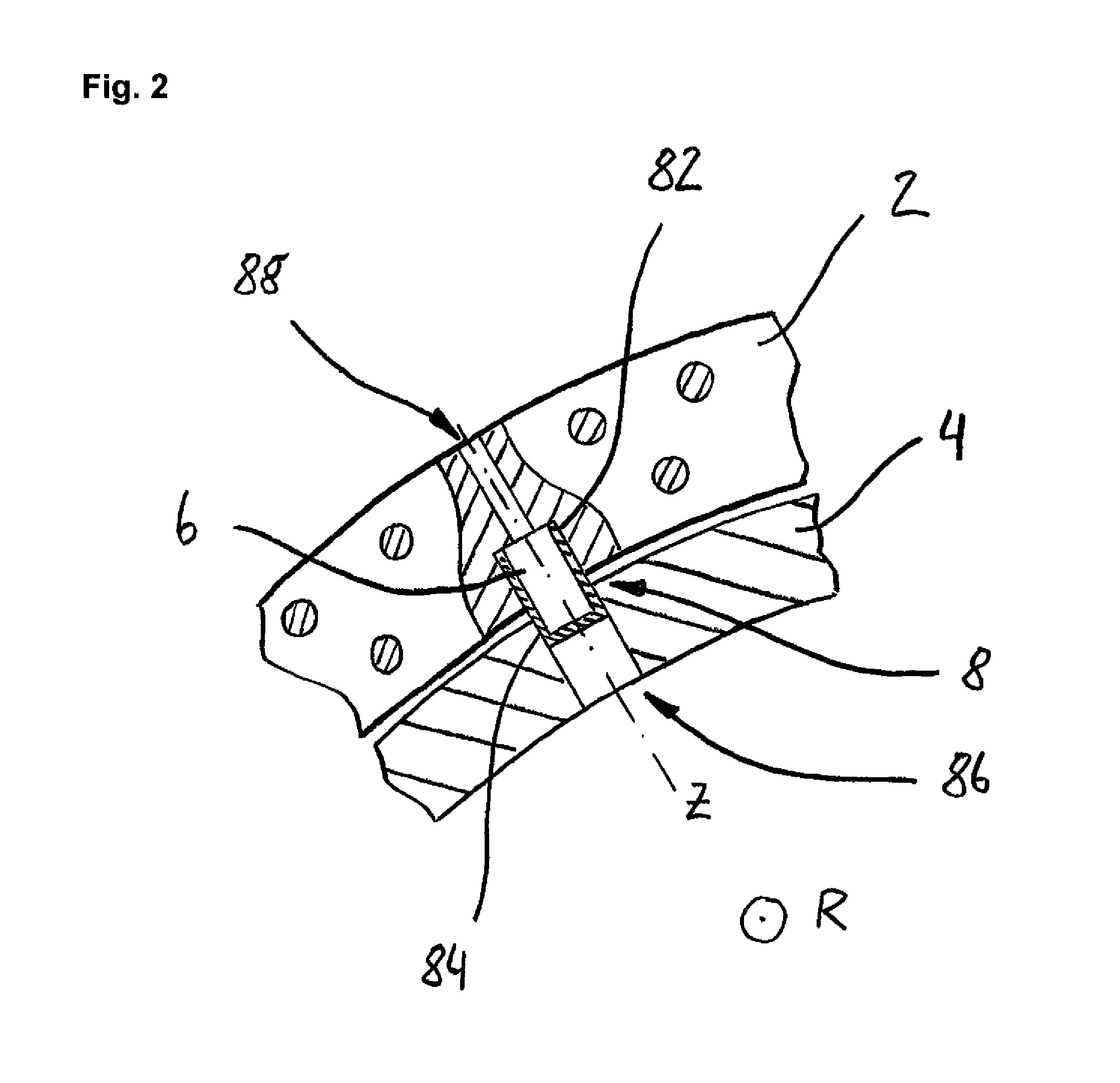
[0053]FIG. 1a shows a preferred embodiment of the brake disc arrangement according to the invention. The friction ring 2 and the mounting adapter 4 are designed or oriented concentrically about the rotational axis R and essentially transverse thereto. The friction ring-side contour region 82 is formed as a recess in the friction ring 2. In the preferred embodiment, the adapter-side contour region 84 is formed as a continuous opening in the mounting adapter 4. The adapter-side contour region 84 together with the friction ring-side contour region 82 along the longitudinal axis Z forms the contour 8. FIG. 1a shows how the connecting element 6 in the first state thereof in a preferred embodiment may be positioned in the contour 8. In order to bring the connecting element 6 into this position, the opening region 86 is used. FIG. 1b shows accordingly that the opening region 86 simultaneously has the function of an access region 88. The connecting element 6 is sketched in the second state ...


PUM

PropertyMeasurementUnit
inner pressureaaaaaaaaaa
outer diameteraaaaaaaaaa
thicknessaaaaaaaaaa

Abstract

A brake disc arrangement for disc brakes comprising a friction ring, a mounting adapter for mounting the brake disc arrangement on a wheel hub, at least one connecting element for connecting the friction ring and the mounting adapter, and at least one contour having a friction ring-side and an adapter-side contour region, wherein the contour is shaped along a longitudinal axis by recesses in the friction ring and the mounting adapter running perpendicular to a rotational axis of the brake disc arrangement, wherein the connecting element may be brought from a first state where the connecting element is arranged inside the contour and a second state where the outer diameter of the connecting element is enlarged, such that the connecting element is connected to the friction ring-side and / or the adapter-side contour region by form fit and / or friction fit.

Description

BACKGROUND OF THE INVENTION[0001]The present invention relates to a brake disc arrangement for disc brakes, for example of land vehicles (such as passenger vehicles, trucks, commercial vehicles or utility vehicles or trailers) as well as a method of manufacturing a brake disc arrangement for disc brakes, also for land vehicles in particular.[0002]Brake disc arrangements of the type in question are well known in the prior art. In most cases, they are designed one-piece, formed of a friction ring and a mounting adapter. “Friction ring” means the actual brake disc, which serves to achieve the braking effect by means of respective brake pads. The mounting adapter in turn is provided in order to connect the friction ring and the wheel hub etc. In the known designs, the friction ring is cast onto the mounting adapter such that the friction ring may expand radially and, thus, an opening-up of the friction ring may be avoided, for example when the latter is subject to great variations in te...

Claims


Application Information

Patent Timeline
Patent Type & Authority Applications(United States)
IPC IPC(8): F16D65/12F16D65/00
CPCF16D65/123F16D2065/1356F16D2065/134F16D65/0043F16D65/12F16D2065/1316F16D2065/136F16D2065/1392F16D2250/0084Y10T29/49947
Inventor DREWES, OLAF
Owner SAF HOLLAND GMBH
Learn More