Dielectric spectroscopy for filtrate contamination monitoring during formation testing

a technology of dielectric spectroscopy and formation testing, which is applied in the direction of detection using electromagnetic waves, instruments, and borehole/well accessories, etc., can solve the problems of high level, compromising the fluid sample that one is trying, and miscibility of filtrate with the fluid sampl

Inactive Publication Date: 2015-02-26
BAKER HUGHES INC
View PDF4 Cites 9 Cited by
  • Summary
  • Abstract
  • Description
  • Claims
  • Application Information

AI Technical Summary

Benefits of technology

[0007]Also disclosed is an apparatus for obtaining a sample of a formation fluid having a filtrate contaminant. The apparatus includes: a carrier configured to be conveyed through a borehole penetrating an earth formation; a downhole fluid extraction device disposed at the carrier and configured to extract a sample of a formation fluid through a wall of the borehole; a dielectric spectrometer disposed at the carrier and configured to transmit electromagnetic energy into the extracted sample at a plurality of frequencies and to measure a plurality of responses to determine a permittivity of the extracted sample fluid as a function of frequency; a processor configured to receive the permittivity of the extracted sample as a function of frequency and to estimate the volume fraction of the formation fluid using a permittivity at a selected frequency in the plurality of frequencies for the sample as measured by the dielectric spectrometer; a sample tank configured to contain the extracted sample; and a controller configured to receive the volume fraction from the processor and to transmit a control signal to the downhole fluid extraction device to stop extracting formation fluid when the volume fraction meets or exceeds a selected setpoint.

Problems solved by technology

Unfortunately, mud filtrate (the liquid portion of the drilling mud or fluid) inevitably enters pores of the rock and, when miscible with the connate (original) fluid, mixes with it and contaminates it, compromising the fluid sample that one is trying to collect.
Miscibility of filtrate with the fluid sample occurs when trying to collect an oil sample in a well that was drilled with an oil based mud.
Traditionally, a filtrate contamination level of less than 10% was required because above that contamination level, any subsequent surface PVT laboratory analysis has a high level of uncertainty, which caused high uncertainty n estimation of reserves, estimation of production rates, compartmentalization analysis, reservoir connectivity analysis, flow assurance, and design of well completion and facilities.
To minimize contamination, oil companies have often pumped fluid from the formation for an hour or two because contamination generally declines with prolonged pumping or, alternatively, they may use a more expensive probe and guard system for pumping.
Some oil companies have pumped for up to 10 to 12 hours just to be on the safe side, which corresponds to a very expensive sample in rig time alone and not counting service company charges to deploy a downhole tool to collect the sample.
However, unchanging measurements could be the result of a dynamic equilibrium between horizontal clean up and recontamination by filtrate coming from above and below the zone being tapped and not necessarily be due to having reached 100% purity connate fluid.
Despite many hours of pumping and almost unchanging measured response when withdrawing oil from the center of a long column of an oil-filled highly permeable sand, some samples have had 30% contamination based on subsequent PVT laboratory gas chromatography.

Method used


Image

  • Dielectric spectroscopy for filtrate contamination monitoring during formation testing
  • Dielectric spectroscopy for filtrate contamination monitoring during formation testing
  • Dielectric spectroscopy for filtrate contamination monitoring during formation testing

Examples


Embodiment Construction

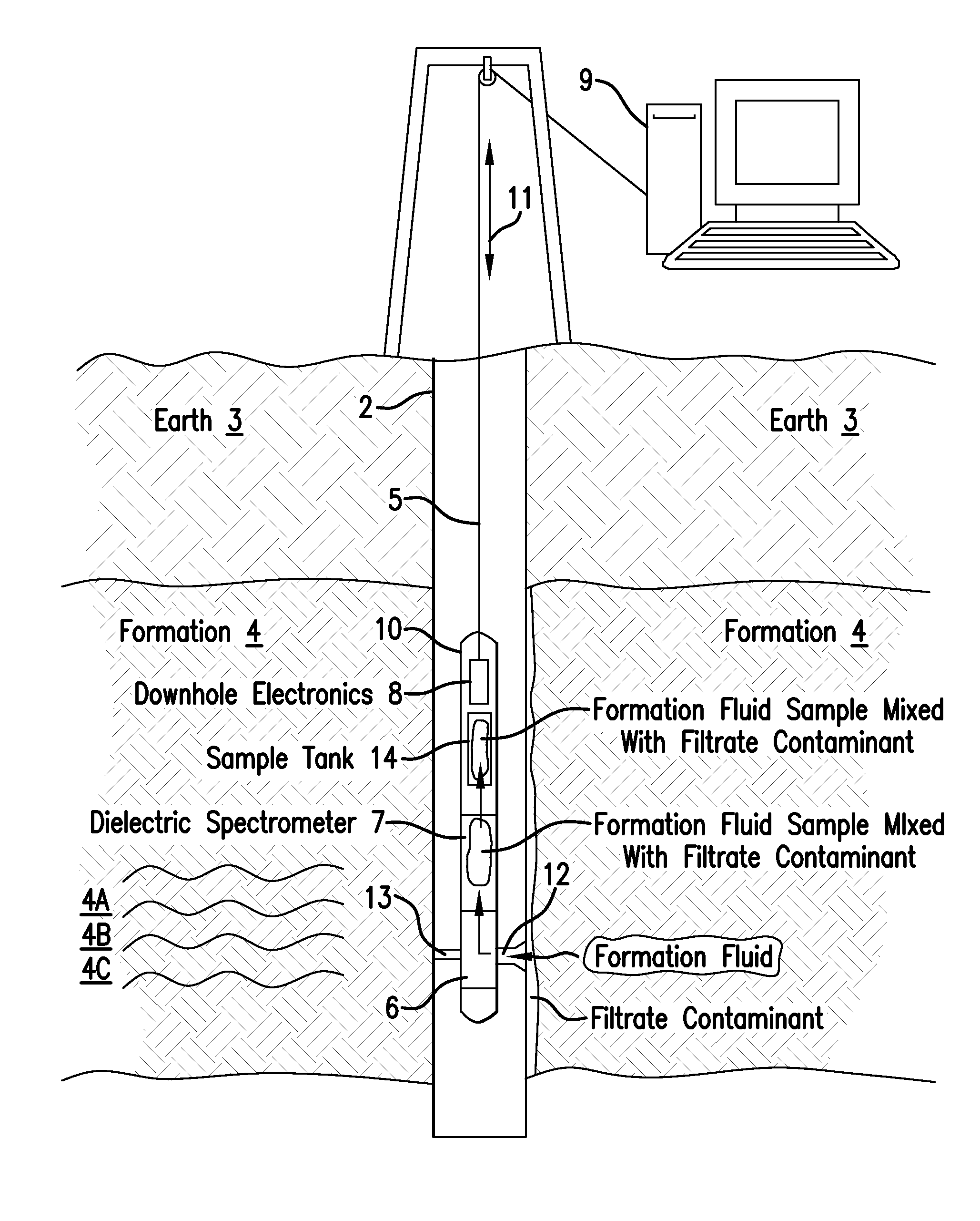
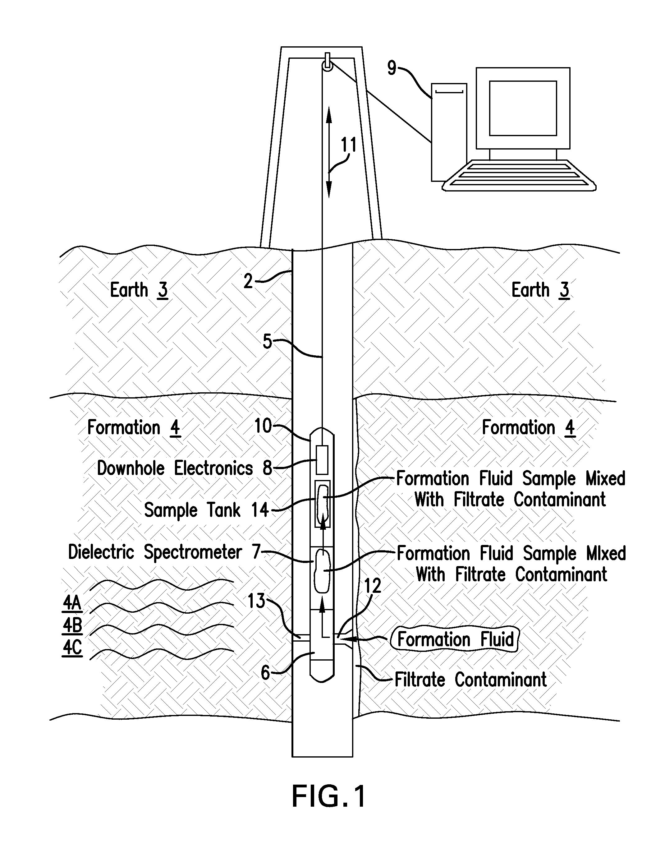
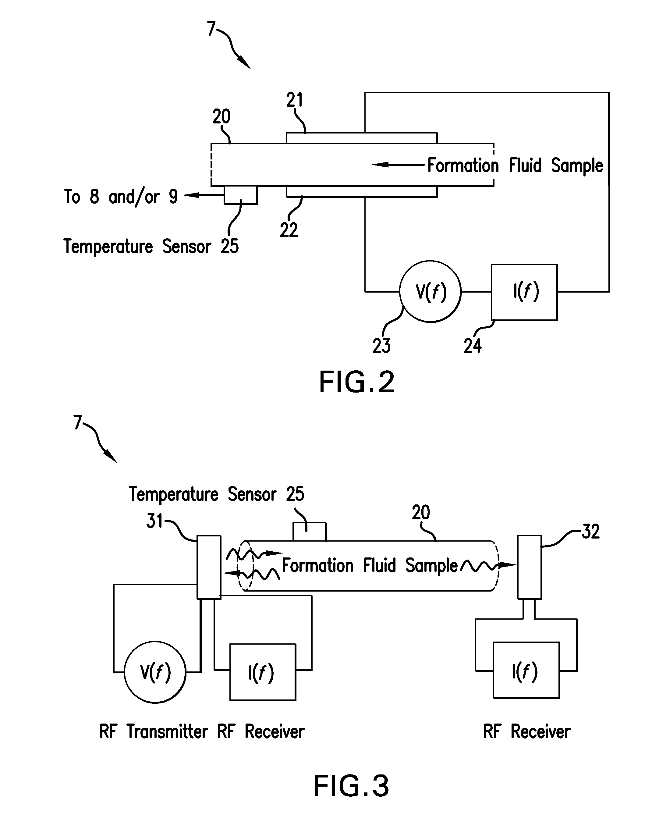
[0022]Disclosed are exemplary embodiments of apparatus and method for estimating a volume fraction of a formation fluid in a sample having a filtrate contaminant. The apparatus and method call for conveying a fluid extraction tool in a borehole penetrating an earth formation of interest containing a formation fluid. The fluid extraction tool is configured to extract a sample of the formation fluid through the borehole wall. Upon obtaining the sample, which may be a mixture of formation fluid and filtrate contaminate, a dielectric spectrometer measures a permittivity (also referred to as a dielectric constant) of the fluid as a function of frequency. From the measured permittivity as a function of frequency, the volume fraction of the formation fluid and / or the volume fraction of the filtrate contaminant may be determined. Based upon the measured contamination percentage, the operator can decide whether the fluid sample has reached sufficient purity to be collected into a sample tank...


PUM


Abstract

An apparatus for estimating a volume fraction of a formation fluid in a sample having a filtrate contaminant includes: a carrier configured to be conveyed through a borehole; a downhole fluid extraction device disposed at the carrier and configured to extract a sample of a formation fluid through a wall of the borehole; and a dielectric spectrometer and configured to transmit electromagnetic energy into the extracted sample at a plurality of frequencies and to measure a plurality of responses to determine a permittivity of the extracted sample fluid as a function of frequency. The apparatus further includes a processor configured to receive the permittivity of the extracted sample as a function of frequency from the dielectric spectrometer and to estimate the volume fraction of the formation fluid using a permittivity at a selected frequency in the plurality of frequencies for the sample as measured by the dielectric spectrometer.

Description

BACKGROUND OF THE INVENTION[0001]Exploration and production of hydrocarbons require accurate and precise measurements of earth formations, which may contain reservoirs of the hydrocarbons. Accurate and precise measurements are important to enable efficient use of exploration and production resources.[0002]Well logging is a technique used to perform measurements of an earth formation from within a borehole penetrating the formation. In well logging, a downhole instrument or tool is conveyed through the borehole. The downhole instrument performs the measurements from within the borehole at various depths typically using a sensor. The measurements are associated with the depth at which the measurements were performed to create a log. In one embodiment, a wireline is used to support the downhole instrument and to transmit measurements to the surface of the earth for processing and recording.[0003]Many types of measurements can be made of the earth formation. In one type of measurement, ...

Claims


Application Information

Patent Timeline
Patent Type & Authority Applications(United States)
IPC IPC(8): G01V3/12E21B49/02
CPCE21B49/02G01V3/12G01N33/24G01N27/026E21B49/088E21B49/0875
Inventor DIFOGGIO, ROCCO
Owner BAKER HUGHES INC
Why Eureka
Try Eureka