
System for storing and outputting thermal energy and method for operating said system

Inactive Publication Date: 2015-03-05
SIEMENS AG
View PDF8 Cites 10 Cited by
  • Summary
  • Abstract
  • Description
  • Claims
  • Application Information

AI Technical Summary

Benefits of technology

The patent describes a method for storing and releasing thermal energy in a plant using a cold accumulator and a cooling unit. The cold accumulator is connected to the cooling unit to precool the cooling medium before it reaches the cold consumer. The cooling unit includes a cooling unit and the cold consumer. The method reduces the energy requirement for cooling and improves the overall energy balance of the plant. The cooling medium can be nitrogen, which is precooled by the cold accumulator to save energy during operation of the cooling unit. This solution is economical and suitable for superconducting components.

Problems solved by technology

This is admittedly no longer available during discharging for the purpose of releasing thermal energy, for which this does not have to be produced separately, however, for operation of the cold consumer which is to be cooled.

Method used


Image

  • System for storing and outputting thermal energy and method for operating said system
  • System for storing and outputting thermal energy and method for operating said system
  • System for storing and outputting thermal energy and method for operating said system

Examples


Embodiment Construction

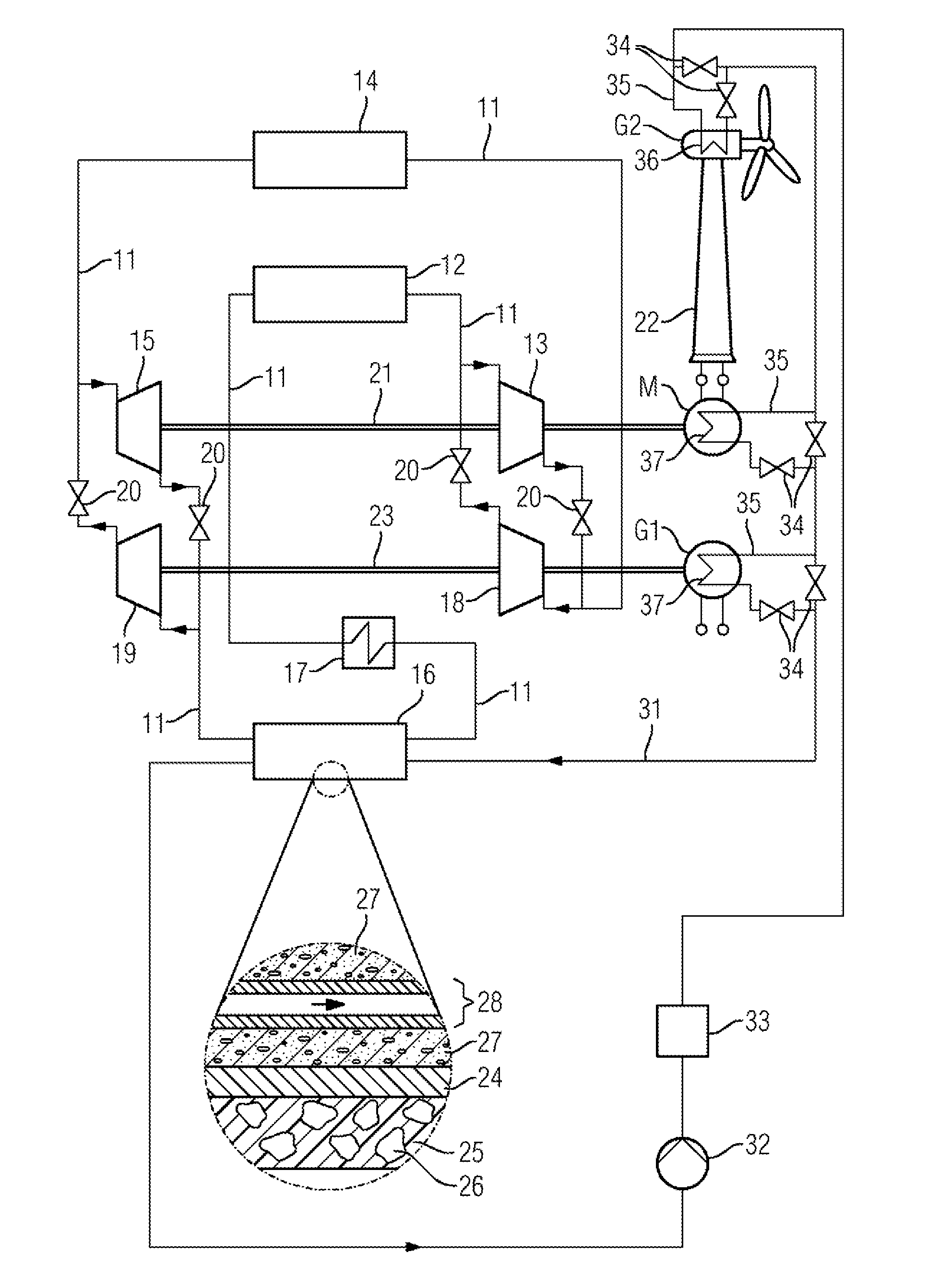
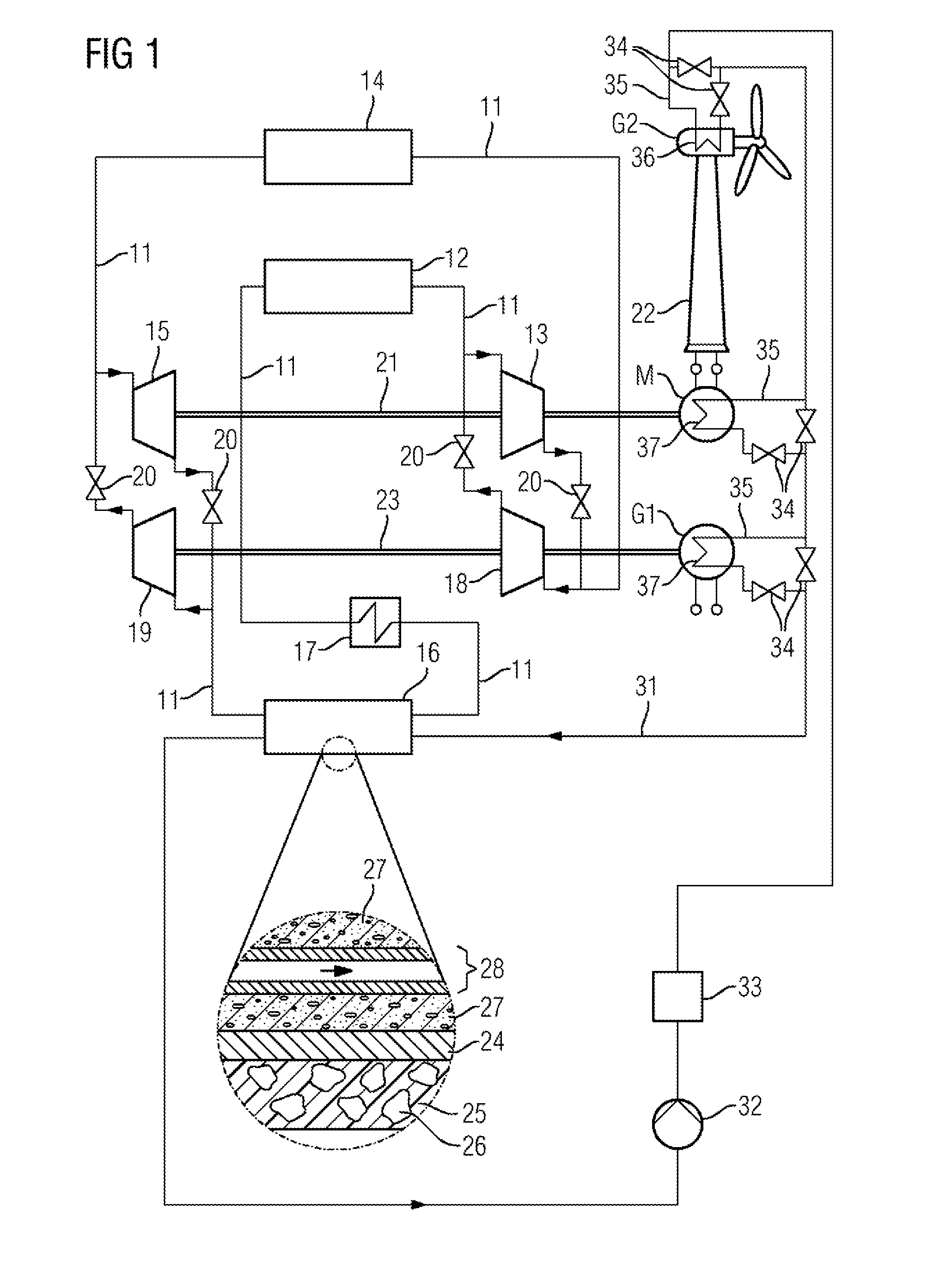
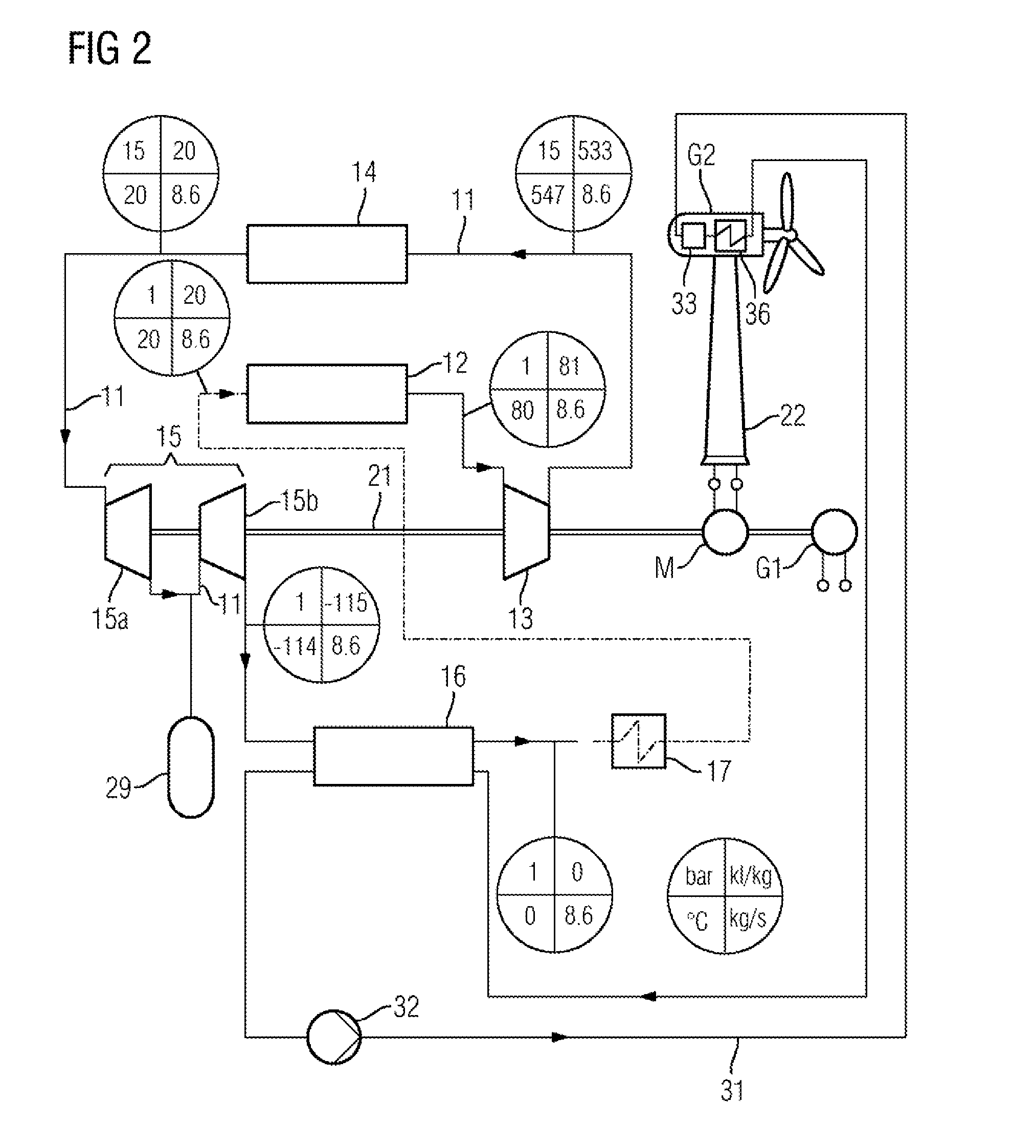
[0024]A plant for storing thermal energy according to FIG. 1 has a line 11 by means of which a plurality of units are interconnected in such a way that a working gas can flow through these. The working gas flows through a low-temperature heat accumulator 12 and then through a first thermal fluid energy machine 13 which is designed as a hydrodynamic compressor. The line then continues to a heat accumulator 14. This is connected to a second thermal fluid energy machine 15 which is designed as a hydrodynamic turbine. From the turbine, the line 11 leads to a cold accumulator 16. The cold accumulator 16 is connected to the low-temperature heat accumulator 12 by means of the line 11, wherein in this line section provision is also made for a heat exchanger 17 via which the working gas can release heat to the environment or absorb heat from the environment (depending on the type of operation).

[0025]In FIG. 1, a closed circuit for the working gas is provided in this respect. However, it is e...


PUM


Abstract

A system for storing and outputting thermal energy and a method for operating the system are provided. The system operates according to the Brayton cycle, wherein a heat accumulator is charged by a compressor and a cold accumulator is charged by turbines. The cycle is reversed for discharging. In addition, the cold accumulator supplies a cooling circuit, which provides the cooling for a superconducting generator by a cooling unit. A favorable generator weight can thereby be advantageously achieved in particular for wind turbines, because the generators are limited regarding the weight thereof due to being housed in the nacelle of the wind power plant. Thus, advantageously higher power can be converted in the wind power plant.

Description

CROSS REFERENCE TO RELATED APPLICATIONS[0001]This application is the US National Stage of International Application No. PCT / EP2013 / 056735 filed Mar. 28, 2013, and claims the benefit thereof. The International application claims the benefit of German Application No. DE 102012206296.3 filed Apr. 17, 2012. All of the applications are incorporated by reference herein in their entirety.FIELD OF INVENTION[0002]The invention relates to a plant for storing thermal energy which has a circuit for a working gas. In the circuit in this case the following units are interconnected in the specified sequence by means of a line for the working gas: a first thermal fluid energy machine, a heat accumulator, a second thermal fluid energy machine and a cold accumulator.[0003]The first thermal fluid energy machine is operated as a working machine and the second thermal fluid energy machine is operated as a power machine, as seen in the flow direction of the working gas from the heat accumulator to the co...

Claims


Application Information

Patent Timeline
IPC IPC(8): F01K3/12F01K3/06
CPCF01K3/06F01K3/12F25B9/06F25B2400/053F25B2400/14F25B2400/24F25B9/004
Inventor KRUGER, URSUSREZNIK, DANIELSTIESDAL, HENRIK
Owner SIEMENS AG
Learn More