
Razor wire

Active Publication Date: 2015-03-05
BIRMINGHAM BARBED TAPE
View PDF12 Cites 2 Cited by
  • Summary
  • Abstract
  • Description
  • Claims
  • Application Information

AI Technical Summary

Benefits of technology

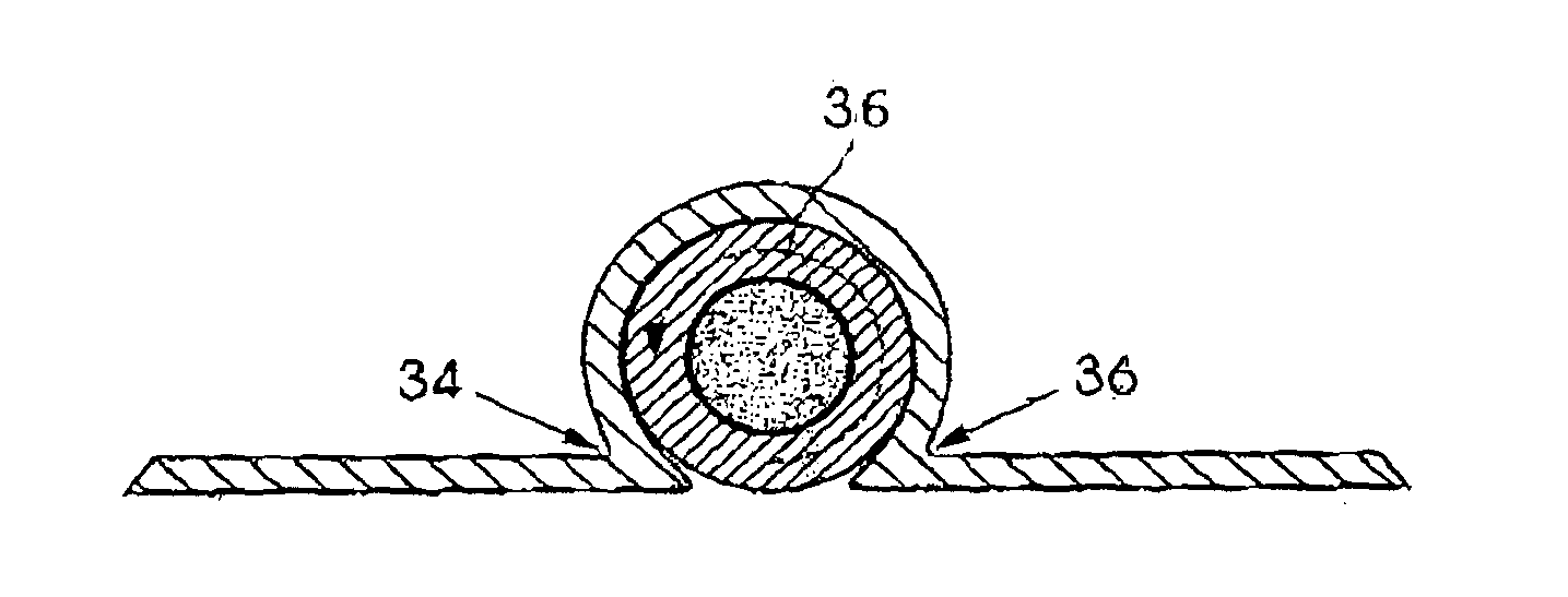
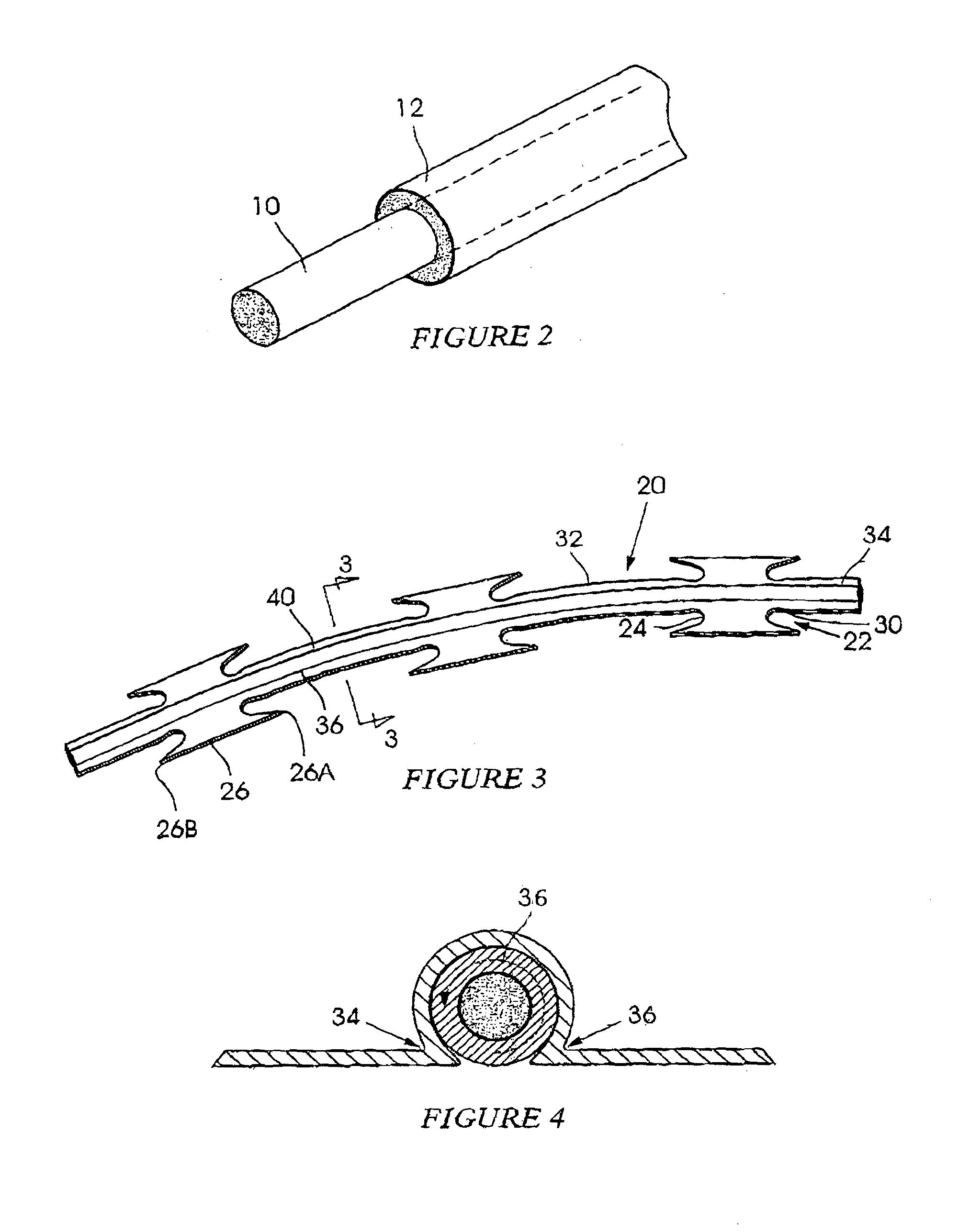
The invention is a barrier wire which has a core wire and an insulating sheath. An elongate strip with barb formations and web sections is wound around the core wire. Each barb formation has a base with two parts: a barb and a neck portion. The strip has two longitudinally extending crimping lines that pass through the neck portion of each barb formation and the web section between them. This creates flanges that prevent damage to the sheath. The angle between the crimp lines is greater than 200 degrees to further prevent damage to the sheath. The core wire is made from a first metal and the elongate strip is made from a second metal that prevents a galvanic reaction between the two metals. The use of aluminum or an aluminum alloy reduces the weight of the barrier wire. The invention allows for effective and reliable use of the core wire for communication signal without adversely affecting the insulation.

Problems solved by technology

This construction, when properly utilised and configured, can present a formidable physical barrier to a would-be intruder.
This negates the physical effect of the barrier.
The inclusion of the signal wire does however present certain technical problems.
In most countries, it is not legally permitted to electrify razor wire, or a similar barrier which has a “snagging” effect.
If an intruder becomes trapped by electrified razor wire, the intruder may be fatally injured.
If the signal wire is used as a direct replacement for the high tensile core wire then, unfortunately, the physical strength of the razor wire is adversely affected to the extent that an intruder can usually simply flatten or push the razor wire aside.
On the other hand if a high tensile core wire is insulated then, when the deterrent strip material is crimped onto the core wire, it is not possible to guarantee that the integrity of the insulation will remain unscathed.
This however can be expensive for it calls for greater quantities of materials.
A different problem presents itself when the razor wire is to be used in a corrosive environment, for example near the sea.
However, when this is done, electrolytic corrosion effects manifest themselves due to the core wire and strip being made from dissimilar metals which are in contact with each other.
This phenomenon impacts adversely on the core wire and the strip.
G82300206 discloses an insulating sheath around a conductor but there is no solution mentioned in the specification which addresses the problem of damage which could be caused to the insulating sheath.

Method used


Image

  • Razor wire
  • Razor wire
  • Razor wire

Examples


Embodiment Construction

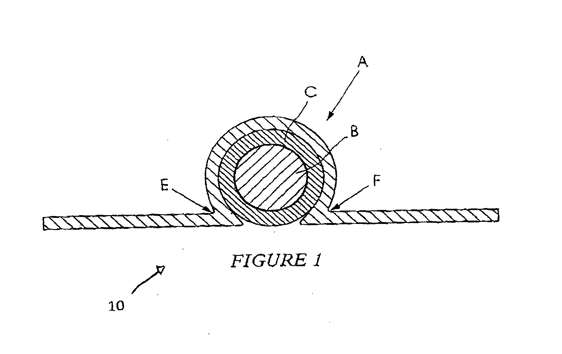
[0032]FIG. 1 of the accompanying drawings is a cross-sectional view of barrier wire A according to a prior art configuration.

[0033]The barrier wire includes a metallic core B surrounded by an insulating sheath C. A deterrent strip D, of a configuration known in the art, is crimped onto the core wire and the insulation. The crimping takes place along opposed lines E and F. At these lines stress zones are produced, inside the insulation, as the strip material is urged towards the core. If the insulation is not strong or thick enough it is prone to collapse in these zones and, as a consequence, the deterrent strip material can come into electrical contact with the core wire B. The invention is intended to address this problem.

[0034]FIG. 2 of the accompanying drawings illustrates in perspective a length of core wire 10 which is used in making razor wire according to the invention. The core wire is a galvanised high tensile steel wire with a nominal diameter of 2 mm and a tensile strengt...


PUM

PropertyMeasurementUnit
Thicknessaaaaaaaaaa
Thicknessaaaaaaaaaa
Thicknessaaaaaaaaaa

Abstract

Razor wire which includes a core wire, an electrically insulating sheath over the core wire and a strip, with a plurality of barbs, which is crimped, along two lines, on opposing sides of the sheath, positioned so that the sheath is not damaged during the crimping process.

Description

BACKGROUND OF THE INVENTION[0001]This invention relates to barrier wire which can be used for deterrent purposes.[0002]Razor wire, a typical example of barrier wire, includes a high tensile steel core to which a deterrent strip, formed with a plurality of sharp spikes, is secured. This construction, when properly utilised and configured, can present a formidable physical barrier to a would-be intruder.[0003]It is, nonetheless, possible for an intruder to sever razor wire using bolt cutters or the like. This negates the physical effect of the barrier. To counter this type of action it is possible to include a signal wire in the razor wire. If the signal wire is severed an alarm will be sounded. The inclusion of the signal wire does however present certain technical problems.[0004]In most countries, it is not legally permitted to electrify razor wire, or a similar barrier which has a “snagging” effect. If an intruder becomes trapped by electrified razor wire, the intruder may be fatal...

Claims


Application Information

Patent Timeline
IPC IPC(8): E04H17/04H01B13/22H01B7/02H01B3/44C22C21/00H01B1/02
CPCE04H17/04C22C21/00H01B13/22H01B7/0275H01B3/44H01B1/02B21F25/00F41H11/08E04H17/045
Inventor SMITH, RONALDCOCHRANE, STEVEN DAVID
Owner BIRMINGHAM BARBED TAPE
Learn More