Round setting technique for pipe end of large-size pipe fitting

A process method and pipe end technology, which is applied in the field of large-scale pipe end rounding technology, can solve the problems of difficulty in butt welding of pipe fittings, poor consistency of pipe end dimensions, and dependence on workers' operating experience. Improve the dimensional accuracy and shape consistency of the pipe end, and the effect of little dependence on operating experience

Inactive Publication Date: 2012-08-22
YANSHAN UNIV
View PDF4 Cites 3 Cited by
  • Summary
  • Abstract
  • Description
  • Claims
  • Application Information

AI Technical Summary

Problems solved by technology

Therefore, the traditional pipe end diameter adjustment method has the following disadvantages: 1. Low work efficiency, which relies heavily on the worker's operating experience; 2. The accuracy of rounding shape is not high; 3. The size consistency of the pipe end is poor, which enhances the butt welding of pipe fittings. difficulty

Method used


Image

  • Round setting technique for pipe end of large-size pipe fitting
  • Round setting technique for pipe end of large-size pipe fitting
  • Round setting technique for pipe end of large-size pipe fitting

Examples


Embodiment 1

[0026] 1. The production of tube blanks

[0027] Pre-bend the longitudinal edge of the milling and welding groove with a specification of 12000mm×3190mm×20mm, and then send the slab into the forming machine to make the slab into an O shape, and perform pre-welding, internal welding, and external welding on the formed tube blank. Welding treatment, welding the longitudinal sides of the tube blank to obtain the tube blank 1 with a specification of Ф1016×20mm.

[0028] 2. Rounding of end face diameter

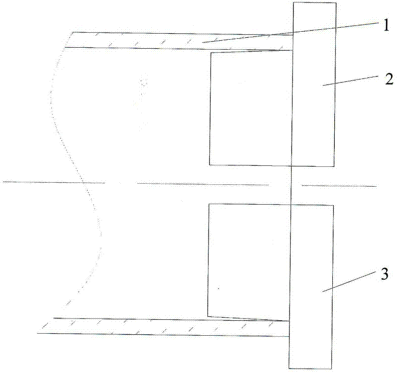
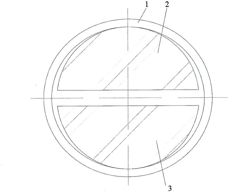
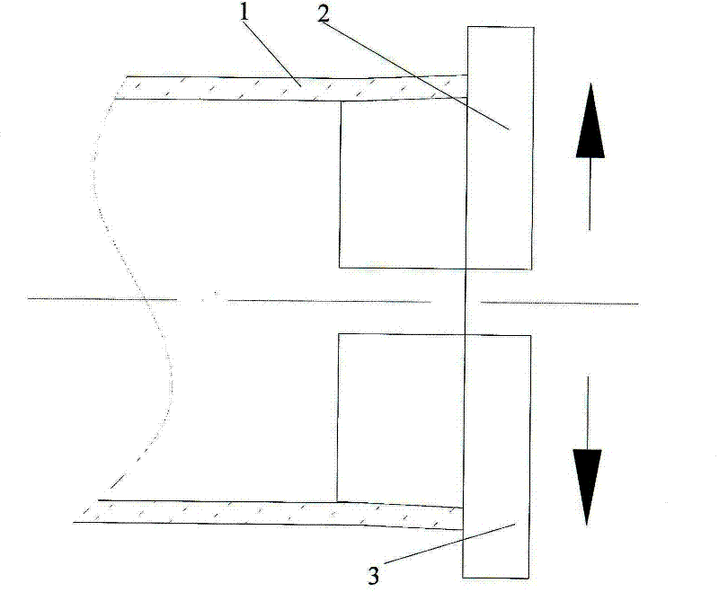
[0029] Convey the tube blank 1 from the track to the internal expansion mold, such as figure 1 , 2 shown. The shape of the expansion mold is as Figure 5 As shown, the axial section of the cone is arc-shaped, the radius of the big end is R460mm, the cone angle is 3°, and the length of the cone is 150mm. Then the two internal expansion molds move towards each other under the drive of the driving device to expand the tube blank, such as image 3 , 4 As shown, make the circumf...

Embodiment 2

[0031] After the welding described in Example 1 is completed, the tube blank 1 is delivered to the expanding four-lobe module by the conveying device, such as Figure 6 shown. The shape of the expanded four-lobe module is as follows Figure 8 As shown, the large end arc radius of the cone part is R460mm, the cone angle is 3°, and the cone length is 150mm. Subsequently, the expansion four-lobe module moves towards each other under the drive of the driving device, and the tube blank is expanded, such as Figure 7 As shown, the circumference dimension of the end of the tube blank is finally made, that is Figure 7 The four times of the sum of C dimension and D dimension is 3222mm. Subsequently, the expanded tube blank is sent by the conveying device between the upper and lower pressing valve molds installed on the general press, and the tube end of the tube blank is pressed and rounded to complete the rounding process of the tube end tube end. The cavity radius of the pressin...


PUM

PropertyMeasurementUnit
lengthaaaaaaaaaa

Abstract

The invention relates to a round setting technique for a pipe end of a large-size pipe fitting. The round setting technique is characterized by comprising the following steps: firstly, preparing an end face of a pipe blank by swelling an inner swelling petal mould so as to cause the uniform peripheral stretching plastic deformation on the end face of the pipe blank, thereby increasing the perimeter of a geometrical neutral layer of the cross section of the pipe end; pressing the end face of the pipe blank by two semicircular petal moulds along the radial direction so as to cause the uniform compressing deformation on the end face of the pipe blank, thereby controlling the last ovality and cross-section perimeter size of the pipe end of the pipe blank; and controlling the molding precision of the pipe end within a tolerance allowed scope. The round setting technique has the advantages that the consistency of shape and size of the pipe end of the pipe blank is increased, the pipeline connection is conveniently performed and the production efficiency is increased at the same time.

Description

technical field [0001] The invention belongs to the field of mechanical processing, and in particular relates to a process method for rounding the ends of large pipe fittings. Background technique [0002] In recent years, with the construction of my country's West-East Gas Pipeline and the development of petroleum, chemical and other industries, the demand for large pipe fittings is increasing, and the quality requirements for large pipe fittings are also gradually increasing. The large pipe fittings in the pipeline mainly include large spiral welded pipes, straight seam welded pipes, elbows, tees, different diameter pipe joints, etc., and the connection methods between the pipe fittings are all butt joint welding. Therefore, in order to ensure the welding quality between the pipe fittings, reduce Welding stress, the size and shape accuracy requirements of the end of the pipe fittings are more stringent than those of the pipe body. On the other hand, the manufacturing proc...

Claims


Application Information

Patent Timeline
Patent Type & Authority Applications(China)
IPC IPC(8): B21D3/00
Inventor 赵军展培培马瑞
Owner YANSHAN UNIV
Why Eureka
Try Eureka