
Fuel Rod Cladding and Methods for Making and Using Same

a technology of fuel rods and claddings, applied in the field of improved, can solve the problems of significant damage, hydrogen generation, zr-alloy cladding loss of tensile strength, impact core coolability, etc., and achieve high tensile and creep strength, maintain fuel rod integrity, and high resistance to oxidation.

Active Publication Date: 2015-03-05
ELECTRIC POWER RES INST INC
View PDF8 Cites 7 Cited by
  • Summary
  • Abstract
  • Description
  • Claims
  • Application Information

AI Technical Summary

Benefits of technology

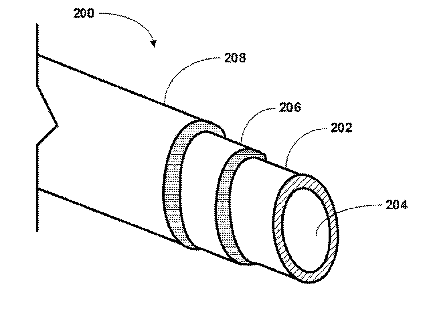
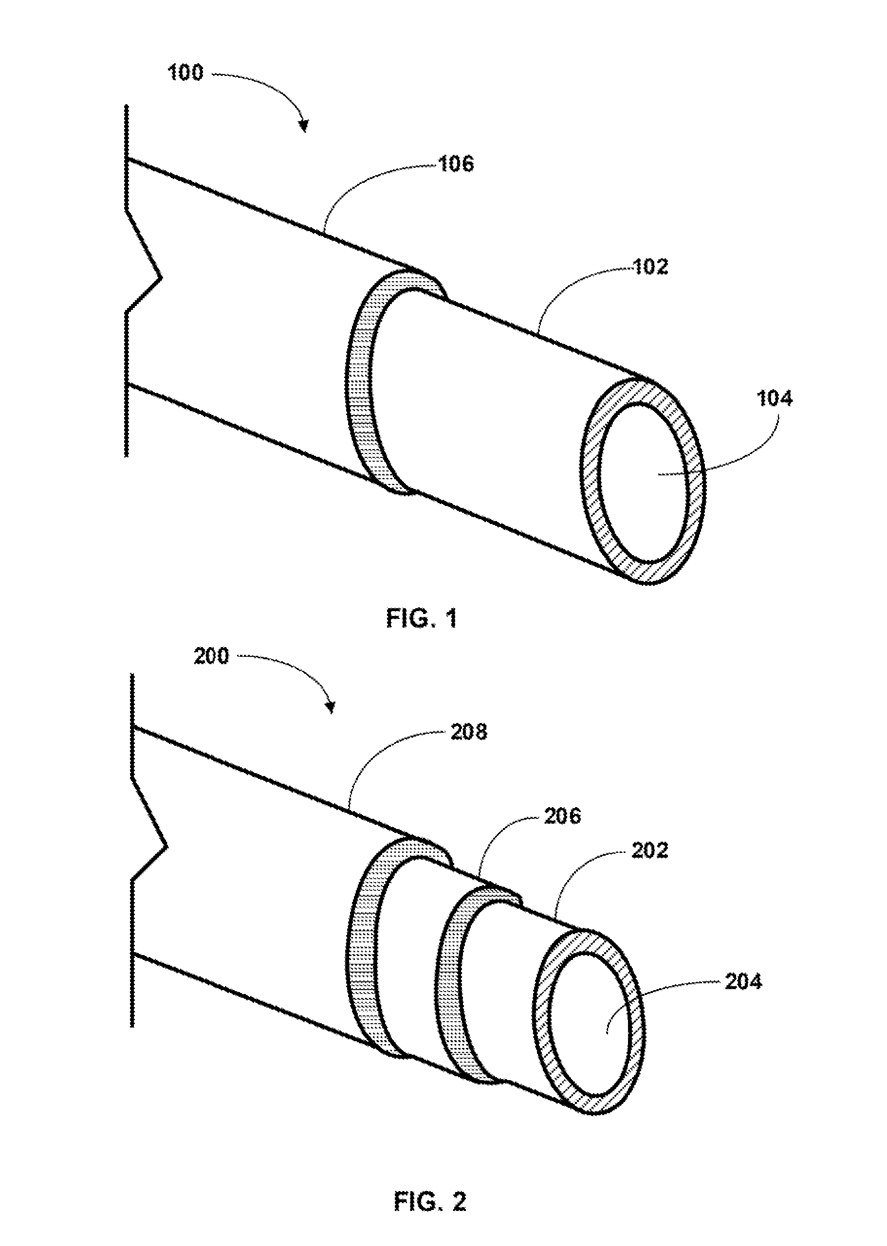
The present invention provides a cladding for nuclear fuel rods that has high strength and can maintain its shape at very high temperatures. It is also resistant to oxidation in steam and can absorb thermal neutrons effectively. The cladding can be made into thin-walled tubes that can be sealed, which is useful for nuclear applications. Molybdenum or molybdenum alloy materials are used for the cladding, which can compensate for a higher neutron cross section by having a thinner wall. This allows for a higher fuel load and reduces the amount of cladding needed.

Problems solved by technology

However, in severe loss-of-coolant accidents, Zr-alloy cladding has certain high-temperature properties that do not favor its ability to maintain fuel rod integrity.
For example, Zr-alloy cladding will undergo rapid oxidation or corrosion in high pressure steam, producing intense heat and hydrogen as the fuel cladding temperature exceeds 700-800° C. Above ˜850° C., Zr-alloy cladding will suffer loss of tensile strength leading to rod burst or defamation, which can impact core coolability.
Therefore, during a loss-of-coolant accident the limitations of current Zr-alloy cladding may lead to significant damage and hydrogen generation.
However, neither the rapid oxidation or corrosion nor the loss of strength can be avoided by modification of the Zr-alloy cladding composition.

Method used


Image

  • Fuel Rod Cladding and Methods for Making and Using Same
  • Fuel Rod Cladding and Methods for Making and Using Same

Examples


Embodiment Construction

[0012]The present invention is more fully described below with reference to the accompanying figures. While the invention will be described in conjunction with particular embodiments, it should be understood that the invention can be applied to a wide variety of applications, and it is intended to cover alternatives, modifications, and equivalents within the spirit and scope of the invention. Accordingly, the following description is exemplary in that several embodiments are described (e.g., by use of the terms “preferably,”“for example,” or “in one embodiment”), but this description should not be viewed as limiting or as setting forth the only embodiments of the invention, as the invention encompasses other embodiments not specifically recited in this description. Further, the use of the terms “invention,”“present invention,”“embodiment,” and similar terms throughout this description are used broadly and are not intended to mean that the invention requires, or is limited to, any pa...


PUM

PropertyMeasurementUnit
weight percentaaaaaaaaaa
thicknessaaaaaaaaaa
temperaturesaaaaaaaaaa

Abstract

In general, the present invention is directed to novel nuclear fuel rod claddings that have better performance characteristics compared to current claddings, particularly during a severe accident, such as a loss of coolant accident. The present invention provides a duplex cladding having two layers, an inner Mo or Mo-alloy layer and a protective layer disposed on the outside of the Mo or Mo-alloy layer. Optionally, the Mo or Mo-alloy layer may have a coating disposed on its inner surface to provide additional capability with the fuel pellets, thereby creating a triplex cladding.

Description

BACKGROUND OF THE INVENTION[0001]1. Field of the Invention[0002]The present invention is directed to an improved fuel rod cladding for a nuclear reactor core. In particular, the present invention is directed to a fuel rod cladding comprising molybdenum and having an outer protective layer and an optional inner layer.[0003]2. Description of Related Art[0004]Current zirconium alloy (Zr-alloy) fuel cladding for light water reactor fuel rods has been optimized to achieve highly reliable performance during normal operations. However, in severe loss-of-coolant accidents, Zr-alloy cladding has certain high-temperature properties that do not favor its ability to maintain fuel rod integrity. For example, Zr-alloy cladding will undergo rapid oxidation or corrosion in high pressure steam, producing intense heat and hydrogen as the fuel cladding temperature exceeds 700-800° C. Above ˜850° C., Zr-alloy cladding will suffer loss of tensile strength leading to rod burst or defamation, which can im...

Claims


Application Information

Patent Timeline
Patent Type & Authority Applications(United States)
IPC IPC(8): G21C3/07
CPCG21C3/07C22C27/04G21C3/20G21C21/02Y02E30/30
Inventor CHENG, BO-CHING
Owner ELECTRIC POWER RES INST INC
Learn More