
Machining head, holder and exchangeable tip cutting tool

a technology of machining head and cutting tool, which is applied in the direction of shaping cutter, tool workpiece connection, manufacturing tools, etc., can solve the problems of reducing the precision of inserted tools, affecting the cutting efficiency of machining head, and increasing the tightening torque during cutting, so as to improve the strength of fastened male threads and improve cutting efficiency. , the effect of high cutting efficiency

Inactive Publication Date: 2015-03-05
HITACHI TOOL ENG LTD
View PDF18 Cites 23 Cited by
  • Summary
  • Abstract
  • Description
  • Claims
  • Application Information

AI Technical Summary

Benefits of technology

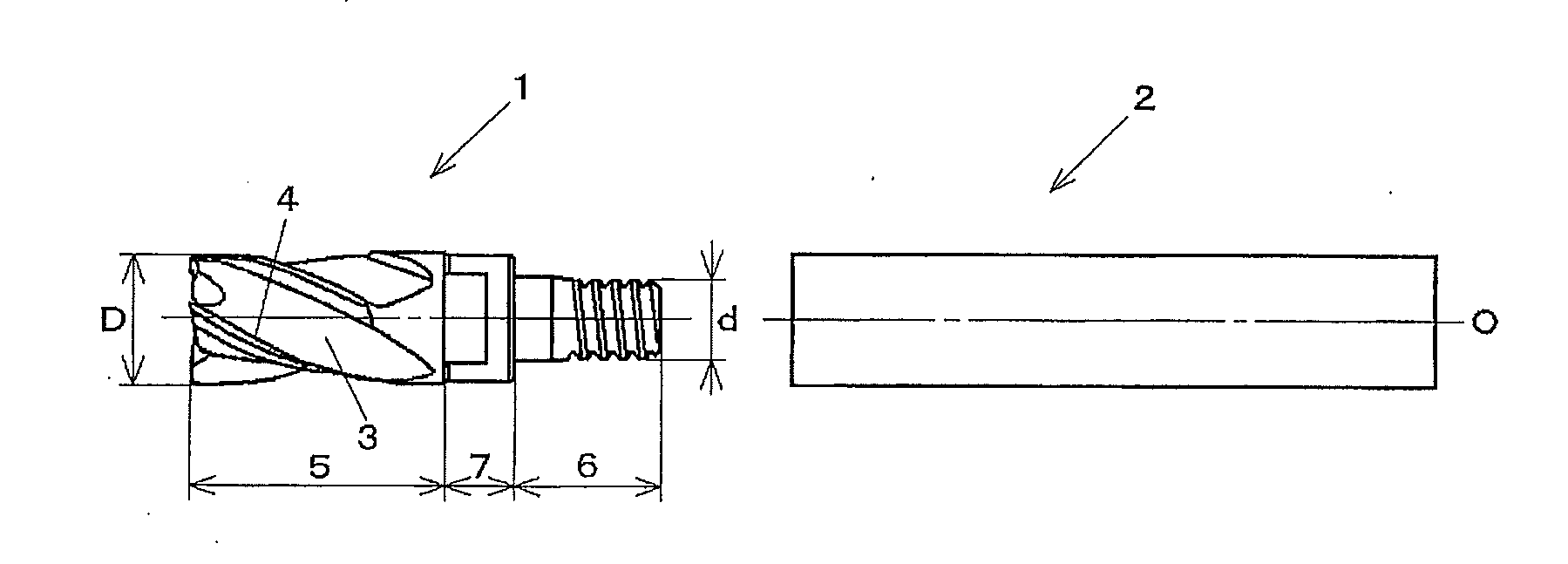
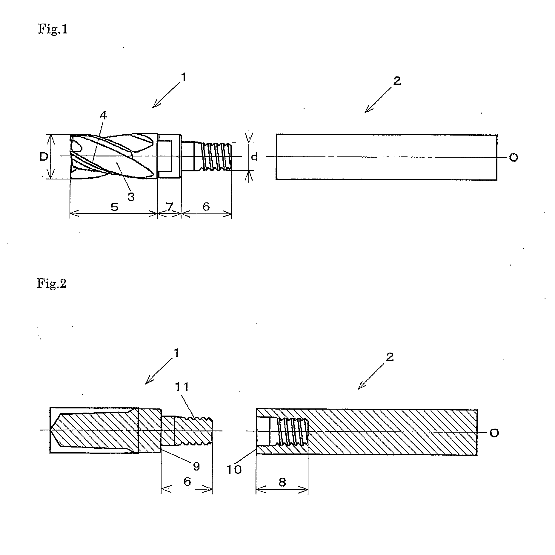
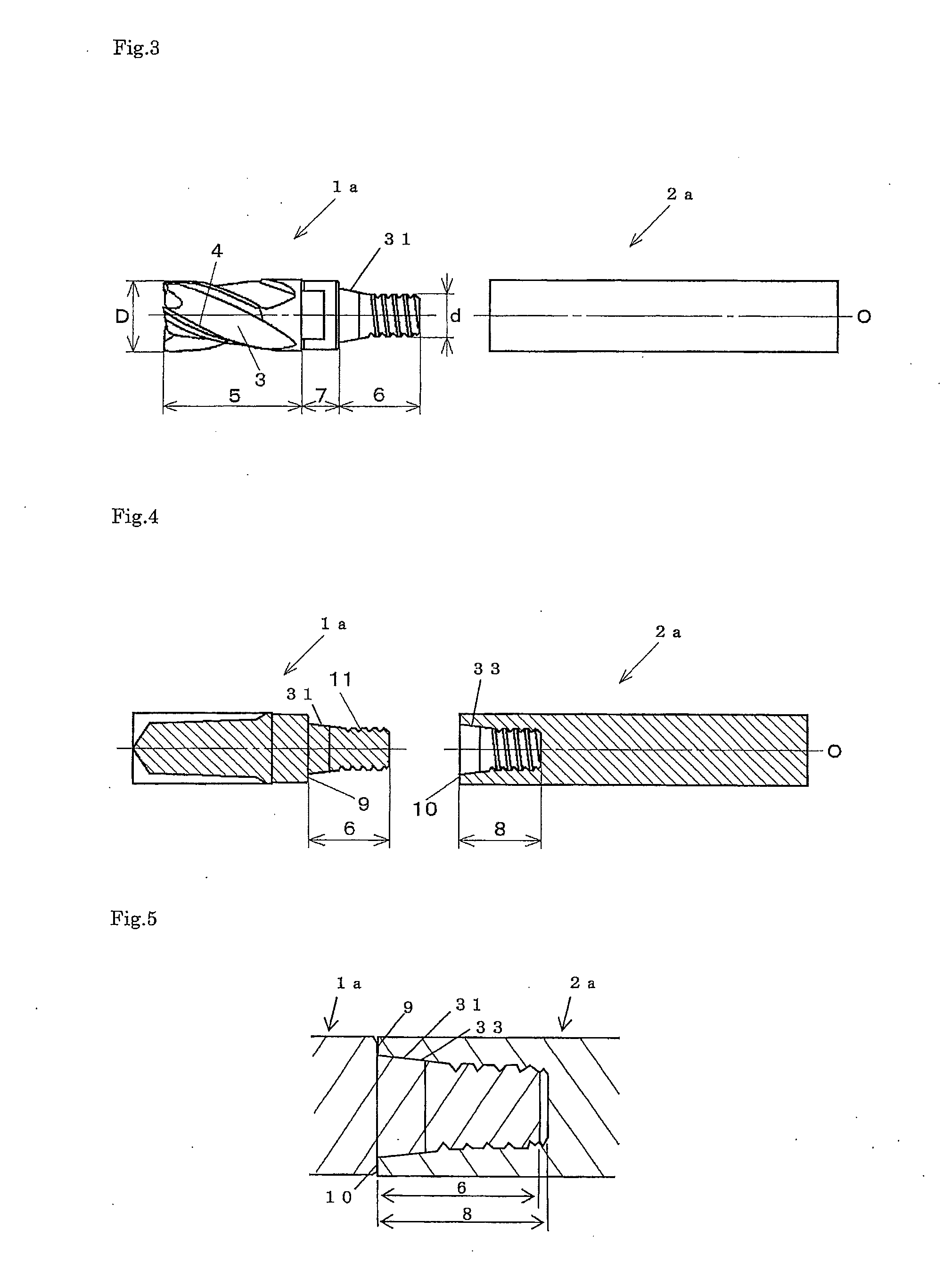
The present invention provides an exchangeable tip cutting tool with a machining head and holder that improves the strength of fastened male threads and highly efficient cutting compared to conventional tools. The tool design reduces damage to the thread ridges due to chattering vibration, resulting in a longer tool life. The thread ridges of the male threaded fastening section have a flank angle of the pressure flank larger than the flank angle of the clearance flank, which improves the overall strength of the male threaded fastening section against the tightening torque. The optimized shape of the thread ridges also increases the strength of individual thread ridge, suppressing fracture or breakage during cutting. The flank angle of the pressure flank is between 10° and 60° to further improve strength and stability during machining. The precision of centering is improved by the large area of the pressure flank and the surface contact of the machining head and holder, resulting in more stable cutting.

Problems solved by technology

Inserted tools have lower precision than solid end mills because of an insertion error due to tip-insertion process and the like, and are commonly used in rough processing.
However, there are problems that fracture or breakage of the threaded section occurs when an enormous load is applied because of the increased cutting load due to abrasion of the tools.
Also, even if there is no fracture nor breakage, there is still such a problem that the tightening torque increases during cutting and detaching the machining head becomes difficult.

Method used


Image

  • Machining head, holder and exchangeable tip cutting tool
  • Machining head, holder and exchangeable tip cutting tool
  • Machining head, holder and exchangeable tip cutting tool

Examples


example 1

[0087]To compare the rigidity of the male and the female fastening sections with different shapes of the threads, following exchangeable tip cutting tools of Embodiment 1 of the present invention, Conventional Example 1, and Comparative Example 1 are prepared and cutting is evaluated.

[0088]For Embodiment 1 of the present invention, a machining head with a male threaded fastening section wherein a flank angle α of the pressure flank is 50°, a flank angle β of the clearance flank is 10°, one pitch P of the thread ridge is 1.5 mm, the crest surface width is 0.408 mm, and the root surface width is 0.408 mm is manufactured. Further, a holder with a female threaded fastening section wherein an angle γ of the screwing surface of the pressure flank is 50°, an angle δ of the screwing surface of the clearance flank is 10°, one pitch P of the thread ridge is 1.5 mm, the crest screwing surface width is 0.408 mm, and the root screwing surface width is 0.408 mm is manufactured. An exchangeable ti...

example 2

[0095]Exchangeable tip cutting tools of embodiments 2 to 9 of the present invention are prepared and cutting is evaluated to compare the change in rigidity of the thread ridges of the male fastening section, the change in rigidity at the rear end of the machining head, and the tool abrasion during cutting at various angular differences between the flank angle α of the pressure flank and the flank angle β of the clearance flank, and between the angle γ of the screwing surface of the pressure flank and the angle δ of the screwing surface of the clearance flank.

[0096]For Embodiment 2 of the present invention, a machining head with a male threaded fastening section wherein a flank angle α of the pressure flank is 50°, a flank angle β of the clearance flank is 45°, the crest surface width is 0.452 mm, and the root surface width is 0.452 mm is manufactured. Further, a holder with a female threaded fastening section wherein an angle γ of the screwing surface of the pressure flank is 50°, a...

example 3

[0110]Exchangeable tip cutting tools of embodiments 10 to 14 of the present invention are prepared and cutting is evaluated to compare the change in rigidity of the thread ridges of the male fastening section, the change in the accuracy of centering when the machining head is screwed with the holder, and the tool abrasion during cutting at various flank angles α of the pressure flank and various angles γ of the screwing surface of the pressure flank.

[0111]For Embodiment 10 of the present invention, a machining head with a male threaded fastening section wherein a flank angle α of the pressure flank is 30°, a flank angle β of the clearance flank is 20°, the crest surface width is 0.764 mm, and the root surface width is 0.764 mm is manufactured. Further, a holder with a female threaded fastening section wherein an angle γ of the screwing surface of the pressure flank is 30°, an angle δ of the screwing surface of the clearance flank is 20°, the crest screwing surface width is 0.764 mm,...


PUM


Abstract

Provided are: an exchangeable tip cutting tool in which breakage of the threaded section and breakage of the thread ridges during installation of the machining head and under increased cutting load during cutting are limited and which is capable of performing machining with high efficiency; and a machining head and a holder to be used in the exchangeable tip cutting tool. The flank angle (α) of the pressure flank (11) is set to be larger than the flank angle (β) of the clearance flank (12); and a holder (2, 2a) having a female threaded fastening section (8) wherein the angle of the screwing surface of the pressure flank is set to be larger than the angle of the screwing surface of the clearance flank.

Description

FIELD OF THE INVENTION[0001]This invention relates to a machining head detachable by screwing, a holder, and an exchangeable tip cutting tool.BACKGROUND OF THE INVENTION[0002]The commonly used cutting tools are solid end mills, which are made of cemented carbide from the tips of the edges to the shanks, and inserted tools, of which the bodies are made of steel and the edges are exchangeable carbide tips. Since solid end mills are formed integrally from the tip to the shank, they have high precision and are commonly used in finishing processing. Inserted tools have lower precision than solid end mills because of an insertion error due to tip-insertion process and the like, and are commonly used in rough processing. Also, inserted tools can be manufactured at low cost compared to solid end mills since only the tips of inserted tools are made of cemented carbide.[0003]In recent years, exchangeable tip cutting tools in which a machining head having a cutting edge can be screwed to a hol...

Claims


Application Information

Patent Timeline
Patent Type & Authority Applications(United States)
IPC IPC(8): B23C5/10B23C5/22B23C5/00
CPCB23C5/109B23C5/006B23C2240/32B23C2210/02B23C5/22B23C5/10B23B31/1122B23C2210/03Y10T407/1906Y10T407/1924Y10T407/1948
Inventor MAEDA, KATSUTOSHIBABA, MAKOTO
Owner HITACHI TOOL ENG LTD
Learn More